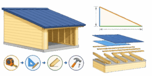
Step onto any modern residential job site, and you will quickly notice a massive architectural shift. The traditional symmetrical gable roof is no longer the automatic default. Single-pitch roofs, also widely known as mono-pitch, shed, or lean-to roofs, have exploded in popularity. They appear on high-end modern homes, backyard studios, cabin designs, and commercial structures. Their appeal is obvious: clean lines, simplified drainage paths, and excellent vaulted ceilings that maximize interior vertical volume.
🏘 However, the apparent visual simplicity of a single-pitch roof is highly deceptive. From a structural engineering standpoint, a mono-pitch roof presents unique structural challenges that differ completely from a standard symmetrical gable system. If you miscalculate the rafter spans, ignore snow accumulation variables, or execute a poor birdsmouth cut, a single-pitch roof will bow, leak, or fail prematurely under extreme weather loads. A tiny 1-inch layout error at the high wall plate translates to a massive discrepancy by the time the framing reaches the low fascia line.
This comprehensive engineering guide breaks down the complete design and layout process for a single-pitch roof. We will explore the structural load mechanics, unpack the exact trigonometric formulas required to cut a perfect rafter, analyze critical field constraints, and review structural span tables using real data.
Table of Contents
The Structural Mechanics of a Mono-Pitch Design
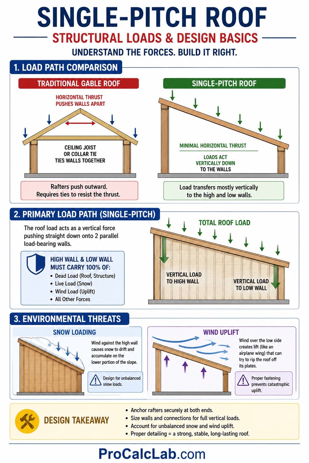
Before pulling out a framing square or a calculator, you must understand the load paths acting on a single-pitch structural frame. In a traditional gable roof, the rafters lean against each other at a central ridge board, creating an outward horizontal thrust that attempts to push the exterior walls apart. This forces builders to install ceiling joists or collar ties to tie the opposing walls together.
A single-pitch roof behaves completely differently. Because all rafters slope continuously in 1 direction from a high wall to a low wall, the horizontal thrust is significantly reduced, provided the rafters are securely anchored at both ends. The structural load acts primarily as a vertical force pushing straight down onto 2 parallel load-bearing walls. This means your high wall and your low wall must be engineered to handle 100% of the roof weight, including temporary weather loads.
From a practical standpoint, the biggest environmental threat to a single-pitch roof is unbalanced snow loading and wind uplift. Because the roof forms a single massive plane, wind hitting the low side can act like an airplane wing, creating a powerful aerodynamic lift that attempts to rip the roof off its plates. Conversely, wind hitting the high wall can cause massive snow drifts to pile up on the lower portions of the slope. Your rafter sizing and fastening schedule must account for these intense physical forces.
The Anatomy of a Single-Pitch Rafter Layout
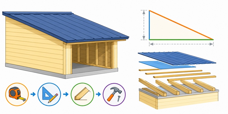
To master the mathematical design, you must understand the precise terminology used by structural engineers and framing carpenters. The entire layout relies on a few critical dimensional lines:
- The Span: The total horizontal distance between the outermost faces of the high and low load-bearing walls.
- The Run: The horizontal distance that a single rafter travels. For a single-pitch roof that rests completely on top of both walls, the run is typically equal to the total span minus the thickness of any exterior wall sheathing.
- The Rise: The vertical distance from the top of the low wall plate to the top of the high wall plate. This dictates the vertical height differential of the building shell.
- The Pitch or Slope: The angle of inclination, traditionally expressed in the US as a ratio of vertical rise inches for every 12 inches of horizontal run. For instance, a 4:12 pitch means the roof climbs 4 inches vertically for every 12 inches of horizontal travel.
- The Line Length: The exact theoretical length of the rafter along its center or top edge, measured from the outer plumb line of the high wall to the outer plumb line of the low wall, excluding any eave or rake overhangs.
The Mathematics of Roof Pitch and Rafter Lengths
To design a single-pitch roof layout that fits perfectly, you must deploy basic geometry and trigonometry. The entire profile forms a right-angled triangle where the horizontal run is the base, the vertical rise is the height, and the rafter line length is the hypotenuse.
Calculating Vertical Wall Rise
If you know your desired roof pitch and the horizontal span of the building, calculating the exact height difference between your high and low framing walls is a straightforward multiplication process.
Rise = Run × (Pitch / 12)
Let us walk through a concrete engineering example. Imagine you are framing a detached workshop with a total horizontal run of 16 feet. To ensure proper rain runoff and matching aesthetics with a nearby garage, you select a 5:12 roof pitch. To find the exact vertical rise required for the high wall, you calculate as follows:
First, divide the pitch value of 5 by 12, which equals 0.4167.
Next, multiply that factor by your horizontal run of 16 feet. 16 multiplied by 0.4167 equals 6.667 feet.
To make this practical for a framing crew using standard tapes, convert the decimal value back to inches. 0.667 feet multiplied by 12 inches equals exactly 8 inches. Therefore, your high wall top plate must sit exactly 6 feet and 8 inches vertically higher than your low wall top plate.
Calculating The Theoretical Line Length
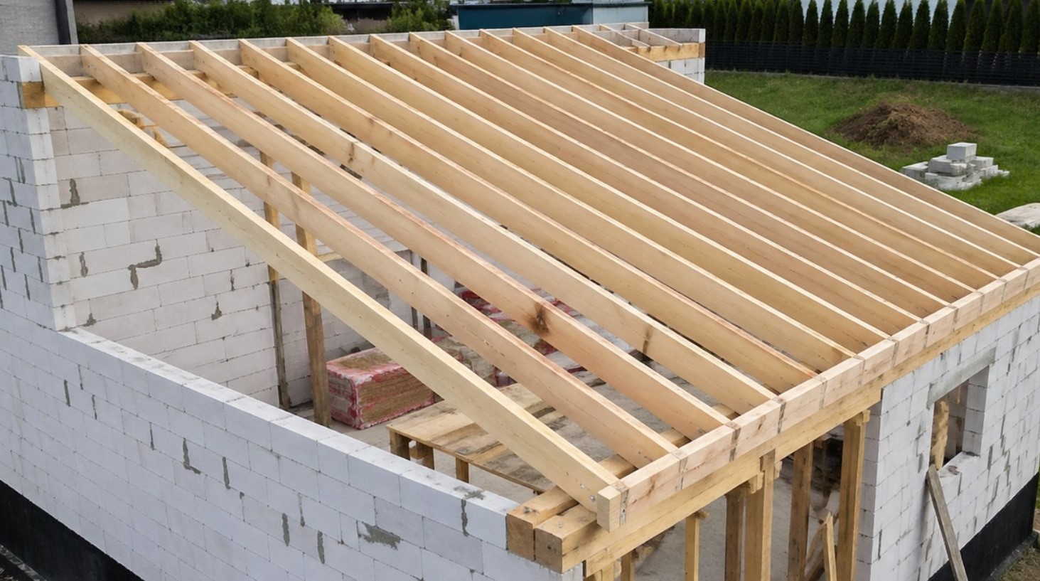
Once your rise and run are locked in, you must use the Pythagorean theorem to calculate the exact line length of the rafter. This tells you the precise size of lumber you need to buy from the lumberyard before factoring in your overhangs.
Line Length = √(Run2 + Rise2)
Using our 16-foot run and our calculated 6.667-foot rise, let us run the math step-by-step:
First, calculate the square of the run. 16 multiplied by 16 equals 256.
Next, calculate the square of the rise. 6.667 multiplied by 6.667 equals 44.45.
Add these 2 values together. 256 plus 44.45 equals 300.45.
Finally, find the square root of 300.45. The result is 17.333 feet.
Converting the decimal portion back to standard measurements, 0.333 feet multiplied by 12 inches equals exactly 4 inches. Your theoretical rafter line length is 17 feet and 4 inches.
Executing the Birdsmouth Cut Calculations
A common mistake during calculations is assuming you can just cut a board to 17 feet and 4 inches and nail it down. In the field, we often see beginners overlook the birdsmouth cut. A birdsmouth cut is a notch cut out of the structural rafter that allows it to sit perfectly flat on top of a horizontal wall plate.
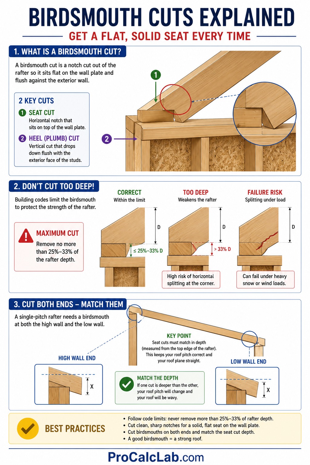
The cut consists of 2 distinct layout lines:
- The Seat Cut: The horizontal notch line that rests directly on top of the 3.5-inch or 5.5-inch wide wooden wall plate.
- The Heel Cut or Plumb Cut: The vertical notch line that drops down flush against the outer face of the vertical wall stud framing.
To maintain structural integrity, building codes stipulate that a birdsmouth cut must never remove more than 25% to 33% of the total vertical depth of the rafter board. If you notch too deeply, you create a major stress concentration point that will cause the rafter to split horizontally right at the inside corner of the wall plate under heavy snow loads.
Furthermore, because a single-pitch rafter slopes across both a high wall and a low wall, you must cut a birdsmouth at both ends of the lumber. The seat cuts must match perfectly in terms of vertical depth relative to the top edge of the rafter. If 1 cut is deeper than the other, your final roof pitch will shift away from your initial calculations, and your roof plane will be wavy.
Reference Material Data for Single-Pitch Roof Design
When selecting your roof covering material, you must respect the minimum pitch requirements established by the International Residential Code. If you install a material on a slope that is too shallow, water will back up under the laps via capillary action and cause catastrophic rot across your structural plywood deck.
The following table tracks the minimum allowable roof pitch angles for standard building materials used across North American residential architecture.
| Roofing Material Type | Minimum Allowable Pitch | Critical Engineering Constraint |
|---|---|---|
| Asphalt Shingles | 2:12 | Requires double underlayment if pitch sits between 2:12 and 4:12 |
| Standing Seam Metal Plates | 0.25:12 | Requires special high-temperature butyl sealant in all seams |
| Screw-Down Metal Panels | 1:12 | Requires structural lap tape and neoprene washer fasteners |
| Clay or Concrete Tiles | 2.5:12 | Requires heavy-duty structural structural roof decking and robust underlayment |
| Built-Up or EPDM Membrane | 0.25:12 | Must have at least 1% slope to prevent water ponding zones |
Once you select your material, you must determine the required structural size of your rafters. Rafter sizing depends entirely on the target species of wood, the grade of the lumber, the spacing between rafters, and the anticipated local environmental loads. The table below represents standard maximum horizontal span limits for Douglas Fir-Larch number 2 structural lumber, assuming a standard residential live load of 20 pounds per square foot and a dead load of 10 pounds per square foot.
Rafter Span Limits – Imperial Measurements
| Lumber Sizing (Nominal) | 12-Inch Center Spacing | 16-Inch Center Spacing | 24-Inch Center Spacing |
|---|---|---|---|
| 2 × 6 inches | 14 feet 4 inches | 13 feet 0 inches | 11 feet 4 inches |
| 2 × 8 inches | 18 feet 10 inches | 17 feet 2 inches | 15 feet 0 inches |
| 2 × 10 inches | 24 feet 1 inch | 21 feet 10 inches | 19 feet 1 inch |
| 2 × 12 inches | 29 feet 3 inches | 26 feet 7 inches | 23 feet 3 inches |
Rafter Span Limits – Metric Measurements
| Lumber Sizing (Actual) | 305-mm Center Spacing | 406-mm Center Spacing | 610-mm Center Spacing |
|---|---|---|---|
| 38 × 140 mm | 4.37 meters | 3.96 meters | 3.45 meters |
| 38 × 184 mm | 5.74 meters | 5.23 meters | 4.57 meters |
| 38 × 235 mm | 7.34 meters | 6.65 meters | 5.82 meters |
| 38 × 286 mm | 8.92 meters | 8.10 meters | 7.09 meters |
Practical Field Application and Troubleshooting
Even with pristine mathematical calculations, executing a flawless single-pitch roof framing layout in the real world presents several major structural hurdles. Below are the primary failure points and design constraints you must watch out for during installation.
Managing Structural Deflection and Sagging
📏 Because single-pitch rafters run continuously over long distances without a central supporting collar tie or ridge beam, they are highly prone to mid-span deflection. Deflection is the physical distance the board bows downward under weight. Building codes typically enforce a strict deflection limit of L/240 for total loads, meaning the maximum allowable sag is the total span length divided by 240.
If you choose a 2 × 8 rafter that is running right at its maximum legal span limit, the roof might pass code but feel incredibly bouncy when an installer walks on it. Over 10 to 15 years, heavy snow events will cause the wood to take on a permanent downward set. This creates a low spot in the middle of your roof plane where water can pool, causing leaks. A smart engineering practice is to always step up 1 size in lumber depth if your horizontal span sits within 10% of the maximum limit shown in the span tables.
Combating Wind Uplift Forces
🌬 As noted earlier, wind blowing over a single-pitch roof creates an aerodynamic low-pressure zone directly above the roof deck, pulling the entire assembly upward. Traditional toe-nailing consisting of driving 3 standard framing nails through the side of the rafter straight into the top plate is completely inadequate for modern engineering standards.
To pass modern building inspections, you must install mechanical hurricane ties at every single rafter connection point on both the high wall and the low wall. These heavy-gauge galvanized steel brackets encase the rafter and bolt directly into the top plates, providing 100s of pounds of continuous resistance against wind lift forces. Furthermore, the high wall rafter connections must feature blocking panels installed between the rafter tails to prevent wind from blowing straight into the interior attic insulation space.
The Nightmare of Cold-Roof Ventilation
🌪 Proper airflow is the single most critical factor in extending the lifespan of a single-pitch roof. In a standard gable roof, air enters through the low soffit vents, flows up through the open attic space, and escapes through a continuous ridge vent at the absolute peak. This natural stack effect keeps the roof structure cold, preventing ice dams in the winter and expelling blistering heat in the summer.
A single-pitch roof lacks an attic. The ceiling is almost always pinned directly to the underside of the structural rafters. If you pack that entire rafter cavity with insulation, you trap moisture against the upper roof deck, leading to immediate wood decay and mold growth. To fix this, you must preserve a continuous 1.5-inch to 2-inch clear air ventilation channel immediately beneath the plywood roof deck. Air must enter through a vented soffit at the low wall, travel unimpeded between every single rafter bay, and exit through a custom mono-pitch ridge vent installed at the top of the high wall.
Summary and Engineering Tools
Designing a single-pitch roof layout requires a careful balance of trigonometric geometry and structural physics. By mastering the relationships between rise, run, and line length, you can confidently calculate rafter lengths and cut birdsmouth seats that transfer vertical loads safely down to your load-bearing wall assemblies. Always cross-check your local snow load ratings against certified lumber span tables, step up your board depth to avoid long-term deflection, and maintain a dedicated air pathway to prevent condensation failure inside your insulation cavities.
Running these geometric extractions and calculating individual rise-to-run deductions manually can consume hours of drafting time, especially when you start adjusting wall plate widths, adding variable overhang lengths, or accounting for different heel cut depths. To streamline your layout phase and verify your dimensions visually before making a single cut with a circular saw, check out our interactive roof and rafter system calculator. By entering your specific building width, pitch profile, and framing spacing, you can instantly generate a precise technical model detailing your layout coordinates, birdsmouth profiles, and exact lumber material lists.
Structural Engineering Literature
- International Code Council. International Residential Code for One- and Two-Family Dwellings. Country Club Hills, IL. The industry standard governing minimum roof slope allowances, rafter span thresholds, and hurricane fastening schedules.
- Thallon, J. Graphic Guide to Frame Construction. The Taunton Press. A comprehensive layout manual detailing birdsmouth cuts, wall plate attachments, and structural eave blocking techniques.
- American Wood Council. Design Values for Joists and Rafters. Leesburg, VA. The definitive technical reference for evaluating maximum span limits based on wood species bending stress ratings and modulus of elasticity.

Markus Fletcher — Structural Design Specialist
Expert in structural integrity, 3D modeling, and applied mathematics. Markus focuses on creating precise tools for construction professionals and DIY engineers.