
Every seasoned engineer has seen it happen on the shop floor. A custom conveyor system or a robotic arm is built, the motor is wired up, the switch is thrown, and the system either stalls instantly or tears itself apart under its own inertia. The culprit is almost always a fundamental misunderstanding of mechanical advantage. Sizing a motor for horsepower or RPM is only half the battle. If you get the gear ratio wrong, you are either starving your system of torque or asking it to rip itself to pieces.

⚙ Calculating gear ratios is the cornerstone of mechanical power transmission. Whether you are designing a simple two-gear reduction for a DIY winch or engineering a multi-stage planetary gearbox for heavy earthmoving equipment, the math remains rooted in the same physical laws. The gear ratio dictates the exact trade-off between speed and torque. You cannot create power out of thin air. You can only manipulate it.
In this guide, we will break down the exact mathematics behind gear trains, starting with simple spur gears and advancing into the complex kinematics of planetary systems. We will look at real-world calculation examples, discuss why exact integer ratios can destroy your machinery, and explore common field failures.
Table of Contents
The Core Theory: Speed, Torque, and Mechanical Advantage
A gear train is essentially a series of rotating levers. When a small gear drives a larger gear, the larger gear turns slower but delivers more rotational force. This rotational force is torque. The relationship between the input and the output is defined by the gear ratio.
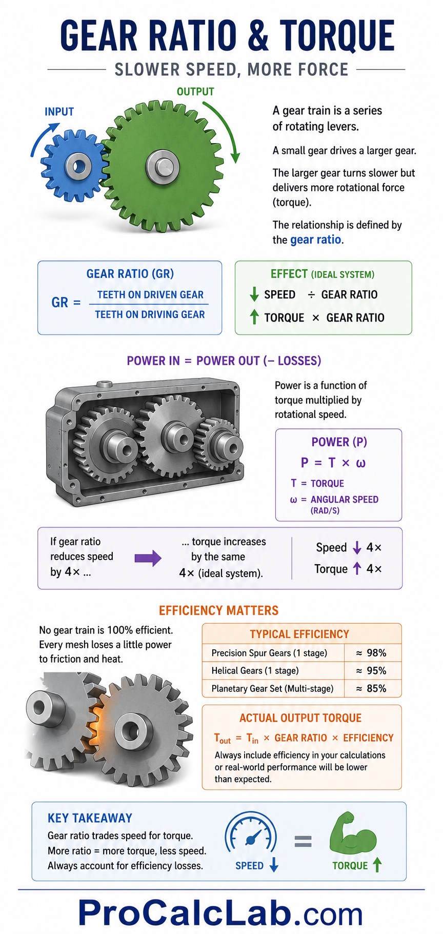
From a practical standpoint, the conservation of energy dictates that the power entering a gearbox equals the power exiting the gearbox, minus whatever is lost to friction and heat. Power is a function of torque multiplied by rotational speed. Therefore, if your gear ratio reduces the rotational speed by a factor of four, it simultaneously multiplies the torque by that exact same factor of four, assuming a perfect system.
In the field, we often see junior designers forget the efficiency penalty. No gear train is 100 % efficient. Every time steel meshes with steel, you lose a fraction of your power. A single stage of precision spur gears might operate at 98 % efficiency. A complex multi-stage planetary setup might drop to 85 %. When you calculate your final torque output, you must factor in this mechanical loss, or your system will underperform when it meets real-world resistance.
Mathematics of Standard Gear Trains
The simplest configuration is a two-gear mesh consisting of a driving gear attached to the power source and a driven gear attached to the load. The driving gear is often called the pinion.
The fundamental formula for calculating the gear ratio of a single stage relies on the number of teeth on each gear. While you can calculate the ratio using pitch diameters, using the tooth count is the industry standard because it leaves zero room for rounding errors.
The Basic Ratio Formula
Ratio = Ndriven / Ndriver
Where Ndriven represents the number of teeth on the output gear and Ndriver represents the number of teeth on the input pinion.
Let us walk through a concrete example. You are building a custom lifting hoist. Your electric motor is fitted with a 15-tooth pinion. This pinion meshes with a large 60-tooth gear attached to the lifting drum. To find your ratio, you divide 60 by 15. The result is 4. This is typically written as a 4:1 ratio.
✍ What does this 4:1 ratio actually mean for your hoist? It means the electric motor must complete four full revolutions to turn the lifting drum exactly one revolution. Consequently, the drum will rotate at one-quarter the speed of the motor, but it will exert four times the lifting torque, neglecting friction.
Idler Gears and Directionality
A common mistake during calculations is factoring idler gears into the final ratio. An idler gear is placed between the driver and the driven gear. Its only physical purpose is to span a physical distance or to reverse the direction of rotation.
If you have a 10-tooth driver, a 30-tooth idler, and a 40-tooth driven gear, you might be tempted to calculate the ratio across all three. However, the math proves the idler is mathematically invisible. The ratio from the driver to the idler is 30/10, which equals 3. The ratio from the idler to the driven gear is 40/30, which equals 1.333. If you multiply these two stages together to get the total ratio, 3 multiplied by 1.333 equals exactly 4. This is the exact same result you get by simply dividing the final 40-tooth gear by the initial 10-tooth driver.
The idler gear changes the rotation direction, but it has absolutely zero impact on your final speed or torque calculations.
Compound Gear Trains
When you need a massive speed reduction, a single gear stage becomes impractical. A 50:1 reduction would require a driven gear fifty times larger than the pinion, which would take up an enormous amount of physical space. To solve this, engineers use compound gear trains.
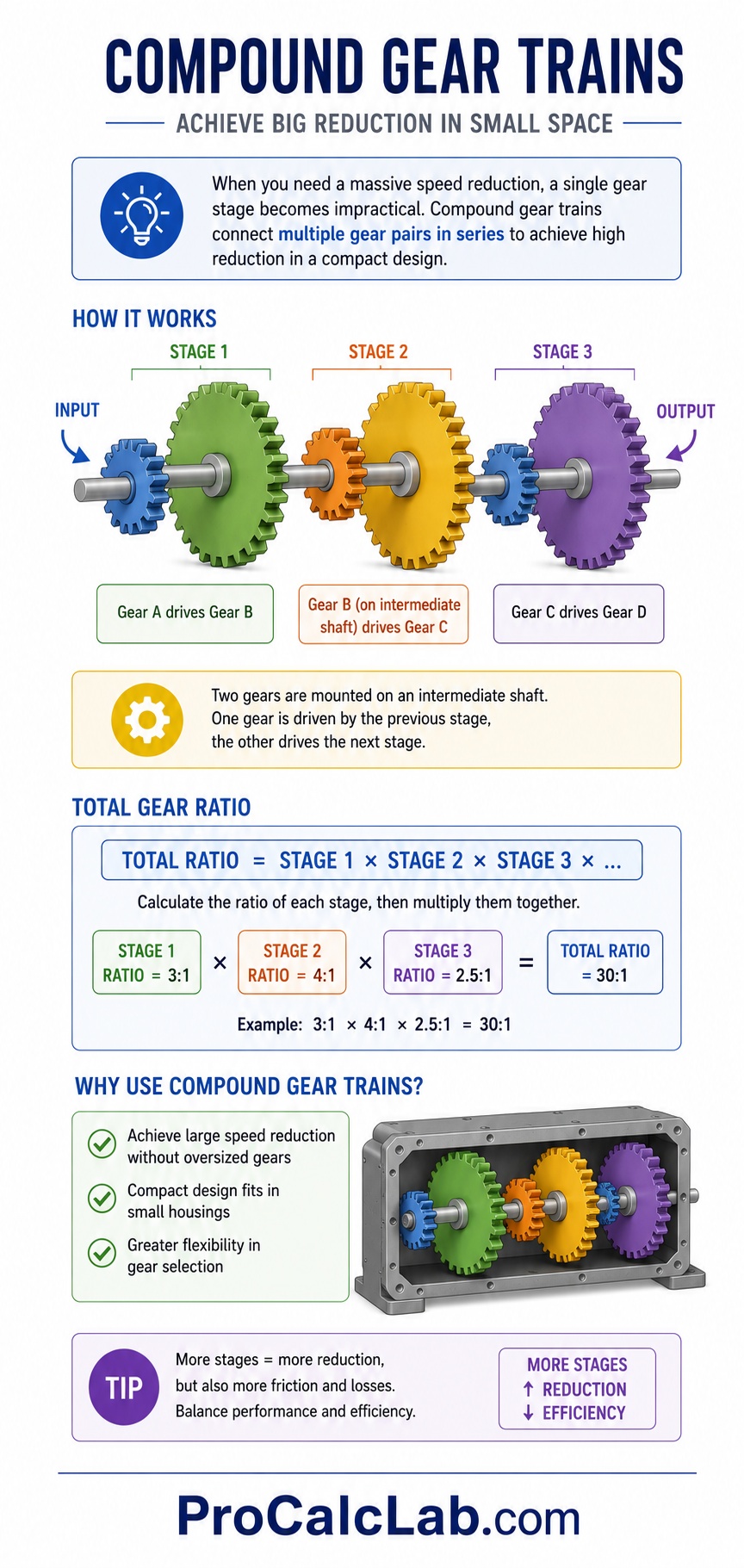
In a compound gear train, multiple gear pairs are connected in series. Two gears are mounted on an intermediate shaft. One gear acts as the driven gear for the first stage, and the second gear acts as the driver for the second stage. To calculate the total gear ratio of a compound system, you calculate the ratio of each individual stage and then multiply those ratios together.
Total Ratio = Stage1 * Stage2 * Stage3
For example, if your first stage has a ratio of 3:1, your second stage has a ratio of 4:1, and your third stage has a ratio of 2.5:1, your total system reduction is 3 multiplied by 4 multiplied by 2.5, resulting in a final ratio of 30:1. The compound setup allows you to achieve massive mechanical advantage inside a very compact housing.
The Concept of the Hunting Tooth
Before moving to planetary systems, we must address a critical design principle known as the hunting tooth. When designing a gear train, engineers intentionally avoid exact integer ratios like 2:1 or 4:1 whenever possible. Instead, they aim for fractional ratios like 4.1:1 or 3.9:1.
⚙ If you use an exact 4:1 ratio, the exact same gear teeth will meet each other every single revolution. If one tooth has a slight manufacturing defect or a burr, it will repeatedly strike the exact same opposing tooth on the larger gear. Over thousands of cycles, this localized wear will destroy the gear.
By adding or subtracting a single tooth on the driven gear to create a non-integer ratio, you ensure that every tooth on the pinion meshes with every single tooth on the driven gear over time. The defective tooth will hunt around the entire circumference, distributing the wear evenly across all teeth and drastically extending the lifespan of the machine.
Mathematics of Planetary Gearboxes
Planetary gearboxes, also known as epicyclic gear trains, represent the pinnacle of compact mechanical power transmission. They are found in automotive automatic transmissions, aerospace actuators, and heavy robotics. They offer massive torque density because the load is distributed across multiple gears simultaneously.
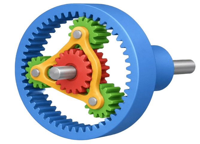
A standard planetary system consists of three main components.
- The Sun Gear: The central gear that rotates on the main axis.
- The Planet Gears and Carrier: Multiple small gears that orbit the sun gear. They are held in a rigid frame called the carrier.
- The Ring Gear: An outer gear with inward-facing teeth that encases the entire assembly.
The mathematics of planetary systems are notoriously tricky because the gear ratio changes entirely depending on which component is held stationary, which component is driven, and which component acts as the output. There are three primary configurations.
Configuration 1: Planetary Mode
In this setup, the Ring Gear is held completely stationary. The input power is applied to the central Sun Gear, and the output is taken from the rotating Planet Carrier.
Ratio = 1 + (Nring / Nsun)
Let us run a real-world calculation. You are designing a wheel hub motor for a rover. Your sun gear has 20 teeth, and your fixed outer ring gear has 80 teeth. Applying the formula, you divide 80 by 20 to get 4. You then add 1. The final gear ratio is 5:1. The planet carrier will rotate in the same direction as the sun gear, but at one-fifth the speed, delivering five times the torque.
Configuration 2: Solar Mode
In this setup, the central Sun Gear is bolted down and held stationary. The input power is applied to the Ring Gear, and the output is taken from the Planet Carrier.
Ratio = 1 + (Nsun / Nring)
Using the same hardware from our previous example, if we lock the 20-tooth sun gear and drive the 80-tooth ring gear, our formula becomes 20 divided by 80, which is 0.25. Adding 1 gives us a final ratio of 1.25:1. This is a very small speed reduction, but it remains highly efficient and compact.
Configuration 3: Star Mode
Here, the Planet Carrier is locked in place so it cannot orbit. The input is applied to the Sun Gear, and the output is taken from the Ring Gear. Because the carrier is fixed, the planet gears act merely as idlers, reversing the direction of rotation.
Ratio = – (Nring / Nsun)
Using our 80-tooth ring and 20-tooth sun, the ratio is simply 80 divided by 20, resulting in 4. However, the negative sign indicates reverse rotation. The output ring gear spins in the opposite direction of the input sun gear at a 4:1 reduction. This configuration is widely used for reverse gears in transmission systems.
Reference Tables for Gear Selection
To assist in your design process, the following table breaks down the kinematic behaviors of a standard epicyclic gear train based on which element is locked.
| Input Component | Output Component | Stationary Component | Speed Effect | Rotation Direction |
|---|---|---|---|---|
| Sun Gear | Planet Carrier | Ring Gear | Maximum Reduction | Same as Input |
| Ring Gear | Planet Carrier | Sun Gear | Minimum Reduction | Same as Input |
| Sun Gear | Ring Gear | Planet Carrier | Moderate Reduction | Opposite to Input |
| Planet Carrier | Sun Gear | Ring Gear | Maximum Overdrive | Same as Input |
When selecting physical dimensions for your gears, you must choose a standard sizing metric. The table below compares common Diametral Pitch classifications used in American engineering design.
| Diametral Pitch (DP) | Typical Application | Tooth Profile Size |
|---|---|---|
| 4 to 8 DP | Heavy machinery, tractors, mining equipment | Very Large / High Strength |
| 10 to 16 DP | Automotive transmissions, industrial conveyors | Medium / Balanced |
| 24 to 48 DP | Hand tools, small appliances, robotics | Small / Precision |
| 64 to 120 DP | Watches, aerospace instruments, medical devices | Micro / Ultra-Precision |
Practical Application and Troubleshooting
Calculating the theoretical ratio on a whiteboard is relatively easy. Ensuring that the gear train survives in the real world is where true engineering begins. Below are the most common failure points and design constraints we see in the field.
Thermal Overload and Efficiency Losses
As mentioned earlier, gearboxes generate heat due to sliding friction at the gear mesh. A single planetary stage might be 97 % efficient. If you stack three planetary stages together to achieve a massive 125:1 reduction, your total efficiency drops. You calculate total efficiency by multiplying the efficiency of each stage together. Therefore, 0.97 times 0.97 times 0.97 equals roughly 0.91, or 91 %.
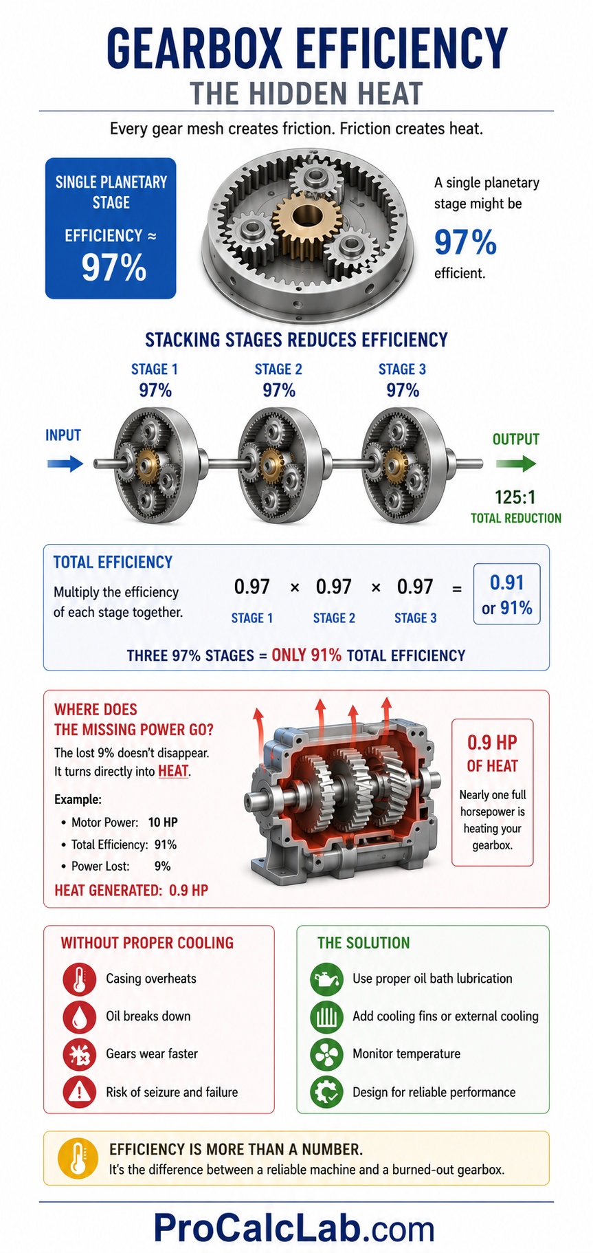
That missing 9 % of your motor power does not just vanish. It turns directly into heat. If your motor is pushing ten horsepower, almost one full horsepower is acting as a heater inside your gearbox casing. Without proper oil bath lubrication and thermal fins, the casing will overheat, the oil will degrade, and the gears will seize.
Backlash and Motion Control
Backlash is the slight physical clearance between mating gear teeth. It is necessary to allow space for lubrication and thermal expansion. However, in precision robotics or CNC machinery, backlash is the enemy. When a motor reverses direction, there is a momentary delay before the gears re-engage on their opposite faces. This creates slop and inaccuracy.
Planetary gearboxes naturally exhibit lower backlash than standard spur gear trains because multiple planet gears are engaged with the sun and ring gears simultaneously. This distributes the load and minimizes free play. If your calculations are meant for precision positioning, you must specify tight-tolerance ground gears and potentially preload the system to eliminate backlash entirely.
Center Distance and Pitch Line Velocity
When designing standard compound gear trains, the physical distance between the shafts must be calculated flawlessly. If the center distance is too tight, the gears will bind, generating massive friction and whining noise. If the center distance is too loose, the gears will only contact at their very tips, leading to immediate catastrophic tooth shear under heavy load.

Furthermore, you must monitor pitch line velocity. This is the physical speed at which the gear teeth are moving through the air. If you spin a large gear too fast, the pitch line velocity exceeds the ability of standard grease or oil to stick to the metal. The lubricant is flung off by centrifugal force, leaving dry steel running against dry steel. High-speed ratios require pressurized oil injection directly at the gear mesh point to prevent melting.
Summary and Engineering Next Steps
🎓 Mastering gear ratios allows you to harness raw rotational power and mold it to fit your exact mechanical needs. Whether you are using standard spur gears to multiply torque or employing complex planetary configurations to achieve massive reductions in a tight space, the mathematical foundation is your most reliable tool. Remember to factor in efficiency losses, avoid exact integer ratios to prevent localized wear, and always account for thermal expansion in your housing.
Calculating planetary kinematics by hand can become tedious, especially when designing multi-stage systems or iterating through various tooth counts to find the perfect speed output. To see these numbers in action and visualize the kinematics without doing the manual arithmetic every time, fire up our interactive planetary gearbox simulator. You can adjust the sun, planet, and ring variables on the fly, lock different components, and instantly see the resulting mathematical ratios and rotational directions applied to a live engineering model.
Engineering Literature and References
- Budynas, R. G., & Nisbett, J. K. Shigley’s Mechanical Engineering Design. McGraw-Hill Education. A definitive text on gear geometry, stress analysis, and mechanical power transmission.
- Oberg, E., Jones, F. D., Horton, H. L., & Ryffel, H. H. Machinery’s Handbook. Industrial Press. The standard reference for diametral pitch standards, backlash tolerances, and center distance calculations.
- American Gear Manufacturers Association (AGMA). AGMA Standard 2001-D04: Fundamental Rating Factors and Calculation Methods for Involute Spur and Helical Gear Teeth. The industry benchmark for evaluating gear strength and durability under load.

David Parry — Senior Engineering Analyst
Specializing in electronics and physics-based simulations with 20+ years of engineering experience. David ensures the mathematical and physical accuracy of the tools at ProCalcLab.