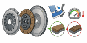
Imagine pushing a heavily loaded commercial truck up a steep 6% highway grade. You step on the throttle to maintain momentum, the engine speed surges, but the vehicle’s road speed slowly begins to drop. Within seconds, a pungent, unmistakable sweet-and-burnt aroma fills the cab. What you are experiencing is a classic mechanical failure: your clutch is slipping. In industrial machinery, heavy equipment, and manual-transmission automotive applications, a slipping clutch represents more than just a loss of operating efficiency. It is a critical breakdown of the kinetic coupling interface that can rapidly destroy the entire powertrain if left unchecked.
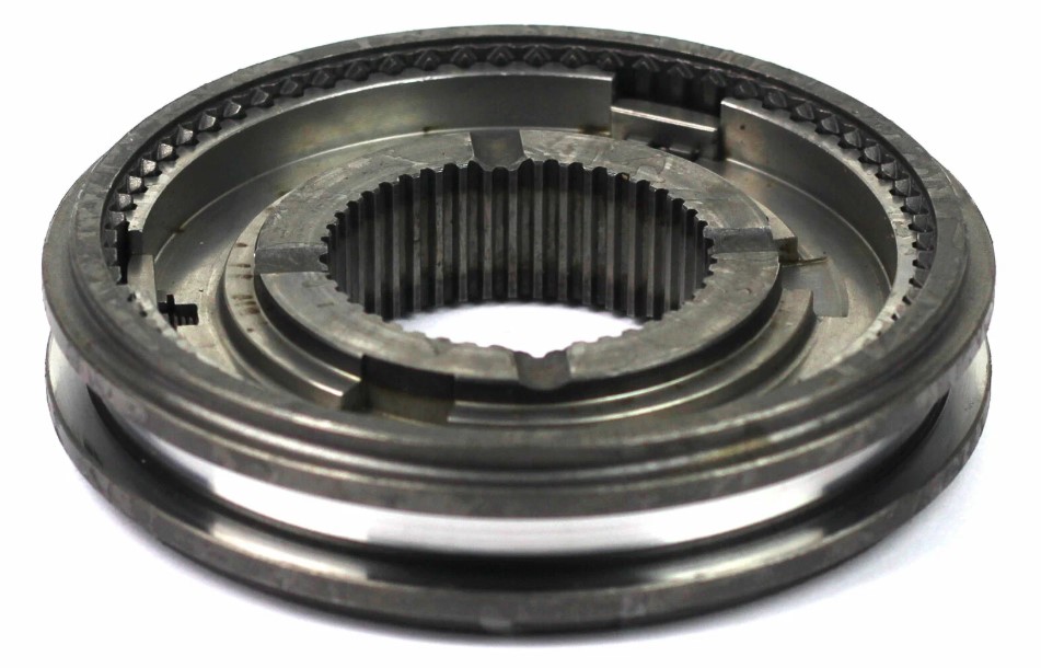
From an engineering standpoint, a clutch is a highly specialized friction-based coupling. It is designed to bridge the rotational gap between a completely stationary transmission input shaft and an engine crankshaft spinning at 1,000s of revolutions per minute. To diagnose why this interface fails, we must look past simple mechanical wear and analyze the structural physics of friction, clamping force, thermal energy transfer, and spring metallurgy. In my 20 years in the field, I have seen countess mechanics replace worn clutch discs only to have the new system fail within 5,000 miles because they ignored the underlying system dynamics.
✍ This guide analyzes the core physics of torque transfer, breaks down the mathematics of clutch capacity, provides 1 concrete engineering calculation, compares the performance of different friction materials, and details how to diagnose clutch slippage in the field.
Table of Contents
The Mechanical Physics of Torque Transfer: Clamping and Friction
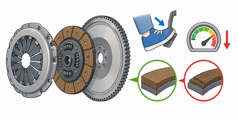
To understand clutch slip, we must analyze the physical interface where torque transfer occurs. When the clutch pedal is fully released, the clutch disc is sandwiched between 2 heavy, rotating iron masses: the engine flywheel and the clutch pressure plate. The primary force driving this assembly is the clamping force generated by the pressure plate’s diaphragm spring, which is a specialized Belleville spring washer.
The torque transfer depends entirely on friction. At the molecular level, no metal or friction lining surface is perfectly flat. When viewed under high magnification, these surfaces consist of tiny microscopic peaks and valleys called asperities. When the pressure plate clamps the clutch disc against the flywheel, these asperities interlock, creating static friction. As long as the applied engine torque remains below the maximum static friction force of this interface, the entire assembly locks together, spinning as a single rigid unit.
However, if the engine’s torque exceeds the static friction capacity, the asperities shear, and the surfaces begin to slide past each other. The system shifts from static friction to kinetic friction. This shift is highly destructive because the kinetic coefficient of friction for standard clutch materials is significantly lower than the static coefficient. Once slip begins, the torque capacity of the coupling drops instantly, causing the slip rate to accelerate.
This slipping conversion of kinetic rotational energy into thermal energy is incredibly rapid. The heat generated at the friction face is governed by the slip speed and the clamping pressure. Because cast iron flywheels and pressure plates have specific thermal conductivity and heat capacity limits, rapid slip can cause localized surface temperatures to spike past 1,000 degrees Fahrenheit in less than 3 seconds. This extreme heat alters the metallurgical properties of the friction plate, causes local thermal expansion, and initiates a dangerous cycle of thermal fade where the friction material loses its grip entirely.
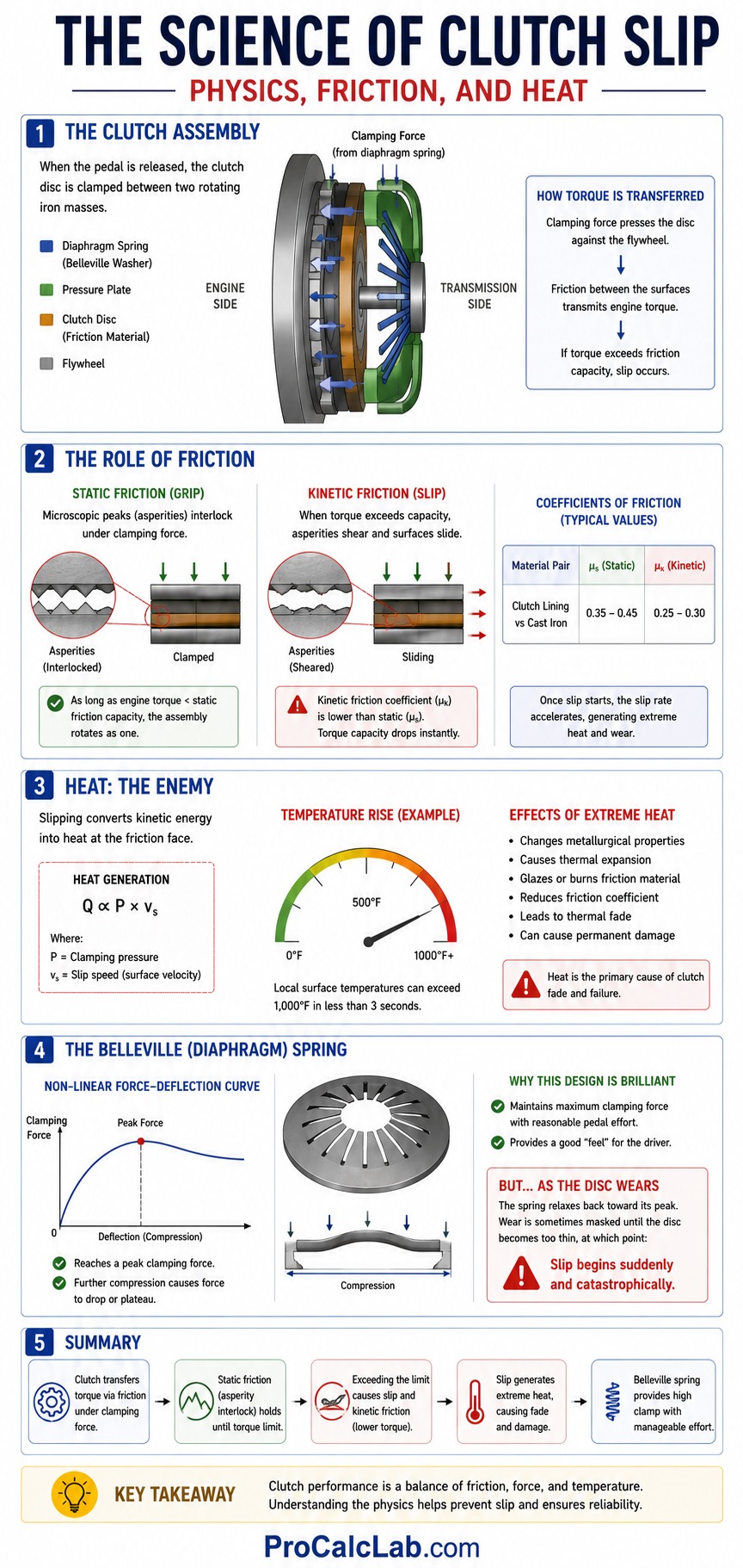
We must also understand the unique physics of the Belleville diaphragm spring used in modern pressure plates. Unlike standard linear coil springs where force is directly proportional to displacement, a Belleville spring has a non-linear force-deflection curve. It reaches a peak clamping force, and then, as you compress it further, the clamping force actually drops or plateaus. This is a brilliant engineering design because it keeps clutch pedal effort manageable for the driver while maintaining maximum clamping force when the clutch disc is fresh. However, as the disc wears and thins, the spring relaxes backward toward its peak, which can sometimes mask wear until the disc suddenly crosses the threshold and slips catastrophically.
The Engineering Mathematics of Clutch Torque Capacity
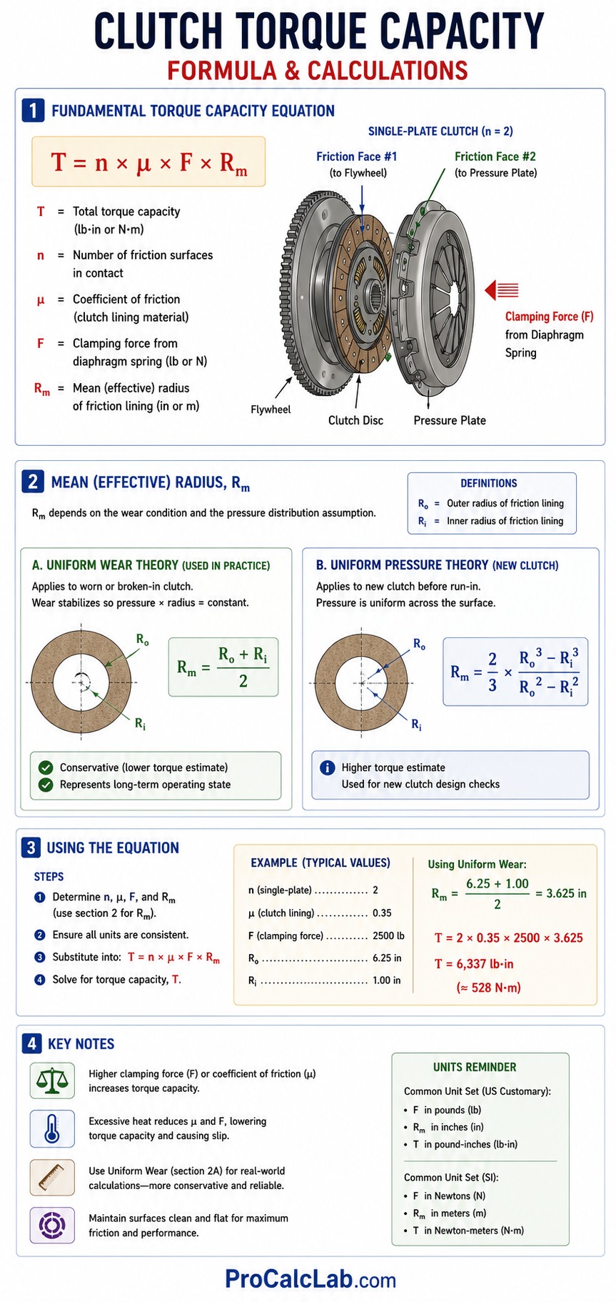
⚙ To design or diagnose a clutch system, engineers rely on mathematical models to calculate the maximum torque the assembly can safely transmit before slipping. The fundamental equation for the torque capacity of a friction clutch is derived from the integration of friction forces across the contact area.
The torque capacity is calculated using the following formula:
T = n × μ × F × Rm
Where the variables are defined as follows:
- T: The total torque capacity of the clutch system, expressed in pound-inches or Newton-meters.
- n: The number of friction surfaces in contact. For a standard single-plate clutch, n equals 2 because the clutch disc has 1 friction face contacting the engine flywheel and a 2nd friction face contacting the pressure plate.
- μ: The coefficient of friction of the clutch lining material.
- F: The clamping force exerted by the diaphragm spring inside the pressure plate assembly, measured in pounds or Newtons.
- Rm: The mean or effective radius of the friction lining, measured in inches or meters.
The calculation of the mean radius, Rm, depends on whether the clutch is new or broken-in. For a worn or broken-in clutch, we assume Uniform Wear Theory. This theory states that after a brief run-in period, the wear across the friction lining stabilizes, meaning the product of pressure and radius remains constant. Under Uniform Wear Theory, the mean radius is calculated as follows:
Rm = (Ro + Ri) / 2
Where Ro is the outer radius of the clutch disc friction lining, and Ri is the inner radius of the clutch disc friction lining.
For a brand-new clutch before the surfaces have fully mated, we use Uniform Pressure Theory, which assumes the clamping pressure is distributed completely evenly across the entire surface:
Rm = (2 / 3) × (Ro3 – Ri3) / (Ro2 – Ri2)
In the field, engineers almost always utilize the Uniform Wear formula because it yields a slightly lower, more conservative estimate of torque capacity, representing the clutch’s long-term operating state.
Step-by-Step Practical Calculation
Let us apply these formulas to a real-world design scenario. Imagine we have a light commercial vehicle with a diesel engine modified to produce 380 pound-feet of peak torque. We need to verify if the existing single-plate clutch can handle this increased output or if it will slip.
To make the calculation compatible with our torque capacity formula, we must first convert the engine torque from pound-feet to pound-inches by multiplying by 12:
Tengine = 380 × 12 = 4,560 pound-inches
Now, let us gather the physical dimensions and specifications of our clutch assembly:
- Outer radius of the clutch disc, Ro: 5.25 inches, representing a 10.5-inch nominal diameter disc.
- Inner radius of the clutch disc, Ri: 3.25 inches, representing a 6.5-inch inner cutout diameter.
- Coefficient of friction, μ: 0.32, typical for a broken-in organic lining under moderate heat.
- Nominal clamping force of the pressure plate spring, F: 1,800 pounds.
- Number of friction surfaces, n: 2.
Step 1: Calculate the mean friction radius, Rm
Using the conservative Uniform Wear Theory:
Rm = (5.25 + 3.25) / 2
Rm = 8.5 / 2 = 4.25 inches
Step 2: Calculate the maximum theoretical torque capacity, Tcapacity
Now we plug our parameters into the main clutch equation:
Tcapacity = n × μ × F × Rm
Tcapacity = 2 × 0.32 × 1,800 × 4.25
Tcapacity = 0.64 × 1,800 × 4.25
Tcapacity = 1,152 × 4.25
Tcapacity = 4,896 pound-inches
Let us convert this value back to pound-feet to make it easy to compare with our engine’s performance rating:
Tcapacity = 4,896 / 12 = 408 pound-feet
Step 3: Analyze the safety margin and potential for slippage
Under ideal operating conditions, the clutch has a maximum static torque capacity of 408 pound-feet. Compared to the engine’s peak torque of 380 pound-feet, we can calculate our safety margin as follows:
Safety Margin = 408 / 380 = 1.07
An operating safety margin of only 1.07, or 7%, is extremely narrow for a mechanical driveline. While this clutch will technically hold under steady-state highway cruising, it is highly vulnerable to slipping during aggressive gear shifts, heavy cargo hauling, or hot ambient operating conditions.
Now, let us calculate what happens if the clutch lining gets hot, causing a mild thermal fade where the coefficient of friction drops by a mere 15%, reducing μ from 0.32 to 0.27:
Tfade = 2 × 0.27 × 1,800 × 4.25 = 4,131 pound-inches
Tfade = 4,131 / 12 = 344.25 pound-feet
Because 344.25 pound-feet of capacity is significantly lower than the engine’s 380 pound-feet of output, the clutch will immediately slip whenever the operator applies full throttle. This calculation highlights how even a minor drop in friction coefficient completely compromises the mechanical coupling.
Performance Characteristics of Friction Materials and Clamping Forces
📊 To design a robust clutch system, we must match the friction material and clamping force to the operating environment. High-performance applications require materials that maintain a high coefficient of friction even under extreme temperatures. However, highly aggressive materials can cause clutch chatter or harsh engagement, making them unsuitable for daily street use.
The following tables detail the engineering properties of the 4 primary clutch friction materials used across the industry, along with typical clamping force specifications.
Table 1: Mechanical Properties of Clutch Friction Materials
| Material Type | Friction Coefficient | Max Continuous Temp |
|---|---|---|
| Organic | 0.25 to 0.35 | 450 F / 232 C |
| Kevlar | 0.35 to 0.40 | 650 F / 343 C |
| Ceramic | 0.38 to 0.45 | 1,000 F / 538 C |
| Carbon-Carbon | 0.40 to 0.50 | 1,500 F / 815 C |
Organic linings, which consist of glass fibers, brass wire, synthetic resins, and organic binders, are the industry standard for daily driving due to their incredibly smooth engagement and quiet operation. However, as Table 1 illustrates, they are highly sensitive to thermal limits. Kevlar offers much higher durability but requires a lengthy break-in period of 500 miles. Ceramic linings, made of sintered copper and iron powders, tolerate extreme heat but engage very aggressively, causing chatter. Carbon-Carbon is the ultimate performance material, used in Formula 1 and aerospace, but it requires significant heat to reach its operational friction coefficient and is extremely expensive.
To support these materials, the pressure plate spring must be calibrated to apply the correct clamping force. The tables below show typical factory clamping force ranges by vehicle class.
Table 2: Clamping Force Requirements – Imperial Units
| Vehicle Class | Clamping Force (lbs) | Typical Application |
|---|---|---|
| Economy Car | 1,000 to 1,400 | Standard commuter driving |
| Sport Compact | 1,800 to 2,400 | Performance street cars |
| Heavy-Duty Truck | 2,800 to 3,800 | Commercial hauling and towing |
Table 3: Clamping Force Requirements – Metric Units
| Vehicle Class | Clamping Force (N) | Typical Application |
|---|---|---|
| Economy Car | 4,450 to 6,230 | Standard commuter driving |
| Sport Compact | 8,000 to 10,680 | Performance street cars |
| Heavy-Duty Truck | 12,450 to 16,900 | Commercial hauling and towing |
Diagnosing Root Causes of Clutch Slippage in the Field
In the field, diagnosing clutch slippage requires a systematic troubleshooting approach. Mechanics often make the mistake of replacing a slipping clutch disc without identifying the underlying root cause, leading to rapid failure of the new components. We must examine the 5 most common engineering failures that cause a clutch to slip.
1. Friction Lining Wear and Thickness Loss
As the friction linings wear down over 10s of 1,000s of miles, the overall thickness of the clutch disc decreases. In a diaphragm clutch system, this thinning forces the pressure plate’s fingers to move outward, altering the angle of the diaphragm spring. In some spring profiles, this movement actually increases clamping force temporarily, but once the wear passes a critical threshold, the spring moves past its peak tension curve. At this point, the clamping force drops off sharply, causing rapid onset of clutch slip.
2. Thermal Glazing of the Friction Lining
When a clutch is subjected to excessive slippage, such as riding the pedal on a hill or executing hard launches, the intense thermal energy melts the organic binders inside the friction lining. This melted material flows to the surface and cools into a hard, highly reflective, glass-like coating. This process is known as glazing. Once a clutch disc is glazed, its coefficient of friction drops by more than 50%, preventing it from transferring torque even if the pressure plate has perfect clamping force.
3. Oil and Fluid Contamination
Even a brand-new clutch will slip if its friction faces are contaminated with automotive fluids. The most common source is a leaking rear main engine crankshaft seal or a failing transmission input shaft seal. When engine oil or transmission fluid leaks into the bellhousing, the spinning flywheel flings the oil outward, coating the clutch disc. The oil acts as a lubricant, reducing the coefficient of friction to near 0. Contaminated clutch discs cannot be cleaned or salvaged because the organic friction material is highly porous and absorbs the oil deep into its structure. The only solution is to seal the leak and replace the disc.
4. Pressure Plate Diaphragm Spring Fatigue
The diaphragm spring in a pressure plate must withstand millions of heat cycles and high mechanical stresses. Over time, the spring steel undergoes metallurgical fatigue, losing its structural temper. As the spring softens, the clamping force it applies to the friction plate drops. This failure is particularly deceptive because the clutch disc may still have plenty of friction lining thickness, yet the system slips under load because the clamping force has dropped below the design threshold.
5. Flywheel Warping and Hot Spots
During periods of extreme slipping, the unequal distribution of heat causes localized thermal expansion across the cast iron faces of the flywheel and pressure plate. These zones of extreme heat turn into a hardened iron phase called martensite, visible as blue or dark gray hot spots on the metal surface. Martensite is extremely hard and has a much lower coefficient of friction than standard gray cast iron. Furthermore, these hot spots distort the flat surface of the flywheel, causing it to warp. A warped flywheel only makes contact with the clutch disc on its high spots, reducing the total effective contact area and accelerating localized wear and slipping.
System Dynamics and Interactive Simulation
A manual transmission system does not operate in a vacuum. The clutch assembly is a dynamic component that must coordinate with the engine’s rotating mass, the transmission gear ratios, and the total mass of the vehicle. When you shift gears, the clutch must manage the rotational inertia difference between the engine flywheel and the transmission input shaft. If the clutch engages too slowly, it slips excessively, generating massive heat. If it engages too quickly, it shocks the driveline, risking gear tooth breakage or axle shaft failure.
Understanding these interactive variables is critical when modifying a vehicle or designing a new industrial drivetrain. To see how these physical parameters interact in real-time, we highly recommend testing your design scenarios using our interactive clutch and gear shift simulator. By running these dynamic scenarios, you can watch exactly how clamping force decay, thermal fade, and material wear affect clutch engagement times, shift quality, and overall driveline survival.
Literature
- Bosch, R. Bosch Automotive Handbook. Bentley Publishers. A comprehensive industry standard covering clutch system design, friction coefficients, and hydraulic actuation mechanics.
- Gillespie, T. D. Fundamentals of Vehicle Dynamics. Society of Automotive Engineers. The definitive academic text detailing how engine torque, tire traction, and clutch engagement interact during vehicle acceleration.
- Erjavec, J., and Thompson, R. Automotive Technology: A Systems Approach. Cengage Learning. A detailed practical guide to manual drivetrain components, pressure plate mechanics, and failure diagnosis.

David Parry — Senior Engineering Analyst
Specializing in electronics and physics-based simulations with 20+ years of engineering experience. David ensures the mathematical and physical accuracy of the tools at ProCalcLab.