Picture a fully loaded 80,000-pound semi-truck stopped at a red light on a 6% uphill grade. The massive diesel engine is idling at 600 revolutions per minute. The transmission is in gear. The brakes are applied. Yet, the engine does not stall. When the light turns green, the driver releases the brakes, presses the throttle, and the truck smoothly accelerates without a traditional mechanical clutch ever being released.

⚙ This mechanical magic is made possible by the torque converter. From a practical standpoint, the torque converter is 1 of the most misunderstood components in modern automotive engineering. Many mechanics view it simply as a fluid clutch that prevents engine stalling. While it certainly performs that job, its true engineering value lies in its ability to physically multiply engine torque during acceleration. It acts as a continuously variable reduction gear, utilizing fluid dynamics to give heavy vehicles the leverage they need to move from a dead stop.
In the field, we often see builders pair massive high-horsepower engines with completely mismatched torque converters, resulting in sluggish launches, overheating transmissions, and shattered input shafts. To truly master powertrain design, you must understand the fluid physics occurring inside that welded steel housing. This guide breaks down the core mechanics of fluid coupling, explains the critical role of the stator, details the mathematics of torque multiplication, and provides real-world troubleshooting strategies for high-performance applications.
Table of Contents
The Core Mechanics of Fluid Coupling
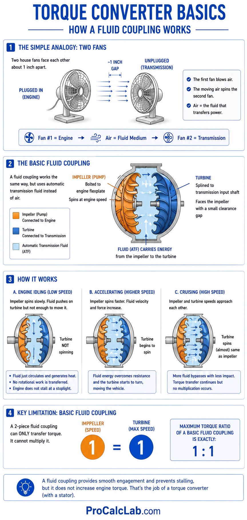
To understand a torque converter, we must first look at a basic fluid coupling. Imagine 2 electric house fans facing each other about 1 inch apart. If you plug 1 fan into the wall and turn it on on high speed, it will blow air directly into the blades of the second unplugged fan. The kinetic energy of the moving air will force the unplugged fan to begin spinning. In this analogy, the first fan is the engine, the second fan is the transmission, and the air is the fluid medium transferring the power.
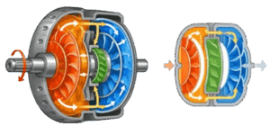
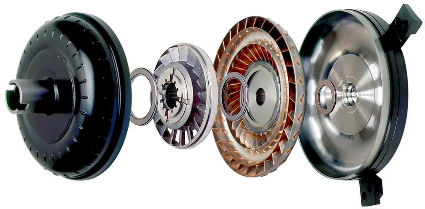
A basic fluid coupling works on this exact principle but uses automatic transmission fluid instead of air. The housing contains 2 primary halves. The first half is the impeller, which is also called the pump. The impeller is physically bolted to the engine flexplate and spins at exact engine speed. The second half is the turbine, which is splined directly to the transmission input shaft. The turbine faces the impeller with a small clearance gap.
When the engine idles, the impeller spins slowly. It flings transmission fluid outward via centrifugal force, pushing it into the turbine blades. At low idle speeds, the force of this fluid is not strong enough to overcome the weight of the vehicle and the holding power of the brakes. The fluid simply washes over the turbine blades, generating a small amount of heat but transferring no rotational work. This state is what prevents the engine from stalling at a stoplight.
As the driver presses the throttle, engine speed increases. The impeller spins faster, drastically increasing the velocity and mass of the fluid striking the turbine. The kinetic energy reaches a tipping point, overcoming the static resistance of the drivetrain, and the turbine begins to spin, moving the vehicle forward. However, a basic 2-piece fluid coupling has a major limitation. It can only transfer torque. It cannot multiply it. The maximum torque ratio of a simple fluid coupling is exactly 1 to 1.
The Stator: The Secret to Torque Multiplication
If you want to move a heavy load quickly, a 1 to 1 ratio is not enough. You need mechanical leverage. This is where the torque converter separates itself from a basic fluid coupling by introducing a 3rd critical component. This component is the stator.
✍ The stator is a small, aggressively finned wheel located in the direct center of the housing, sandwiched tightly between the impeller and the turbine. Its sole engineering purpose is to redirect the fluid returning from the turbine back into the impeller in a specific direction.
In a system without a stator, fluid exits the turbine spinning in the opposite direction of the engine rotation. If this fluid hits the engine-driven impeller, it fights the engine, wasting power and creating massive heat. The stator solves this problem. It is mounted on a 1-way sprag clutch connected to the stationary transmission pump support. This 1-way clutch allows the stator to spin freely in 1 direction but locks it down solid in the opposite direction.
When you launch a vehicle from a dead stop, fluid exits the turbine with extreme force and hits the front face of the stator blades. Because of the fluid direction, the 1-way clutch locks the stator dead still. The curved blades of the stationary stator catch the fluid and force it to execute a 180-degree U-turn. The fluid is literally bounced off the stator and thrown back into the impeller in the exact same direction the engine is already spinning.
This redirected fluid gives the impeller a massive rotational boost. The engine does not have to work as hard to spin the impeller because the returning fluid is acting like a tailwind. This phenomenon multiplies the torque applied to the turbine. Depending on the exact angle of the internal fins, a torque converter can multiply engine torque by a factor of 1.8 to 2.5 during the initial launch phase.
Vortex Flow Versus Rotary Flow
The physical path the fluid takes inside the converter changes based on vehicle speed. When the vehicle is stopped and the engine is revved, the fluid travels in a tight, violent circular path from the impeller, across the gap into the turbine, down into the stator, and back into the impeller. This high-velocity looping motion is called vortex flow. Vortex flow is where maximum torque multiplication occurs.
🏎 As the vehicle accelerates and the turbine speed begins to catch up to the impeller speed, the fluid path changes. Because both halves are now spinning at roughly the same RPM, centrifugal force throws the fluid outward to the perimeter of the housing. The fluid begins traveling in a solid mass along with the housing. This is called rotary flow.
When rotary flow is achieved, the fluid is no longer hitting the front of the stator blades. Instead, it strikes the back of the blades. This unlocks the 1-way clutch, allowing the stator to freewheel along with the fluid mass. At this exact moment, known as the coupling point, torque multiplication ceases. The converter returns to a 1 to 1 fluid coupling ratio, operating at roughly 90% efficiency with 10% fluid slip.
Establishing Engine Baselines Before Selection
Before doing any torque converter math, you have to know what the engine in front of it is actually capable of producing. A torque converter that acts aggressively behind a 600 horsepower big block will feel incredibly soft and sluggish behind a 250 horsepower 4-cylinder engine, even if the physical converter is identical.
To accurately match a converter, you must establish baseline engine output variables. Engineers often use tools like our interactive engine power and displacement calculator to determine theoretical horsepower peaks and volumetric efficiency before finalizing any transmission specifications.
Once you know exactly how much torque the engine makes at specific RPM ranges, you can accurately calculate the resulting forces applied to the transmission input shaft.
The Mathematics of Power Transfer
In mechanical engineering, power is a function of torque and rotational speed. To understand how the converter multiplies this force, we rely on standard rotary equations. The relationship between horsepower, torque, and RPM is governed by a constant of 5252. This constant is derived by dividing 33000 foot-pounds per minute by 2 times pi.
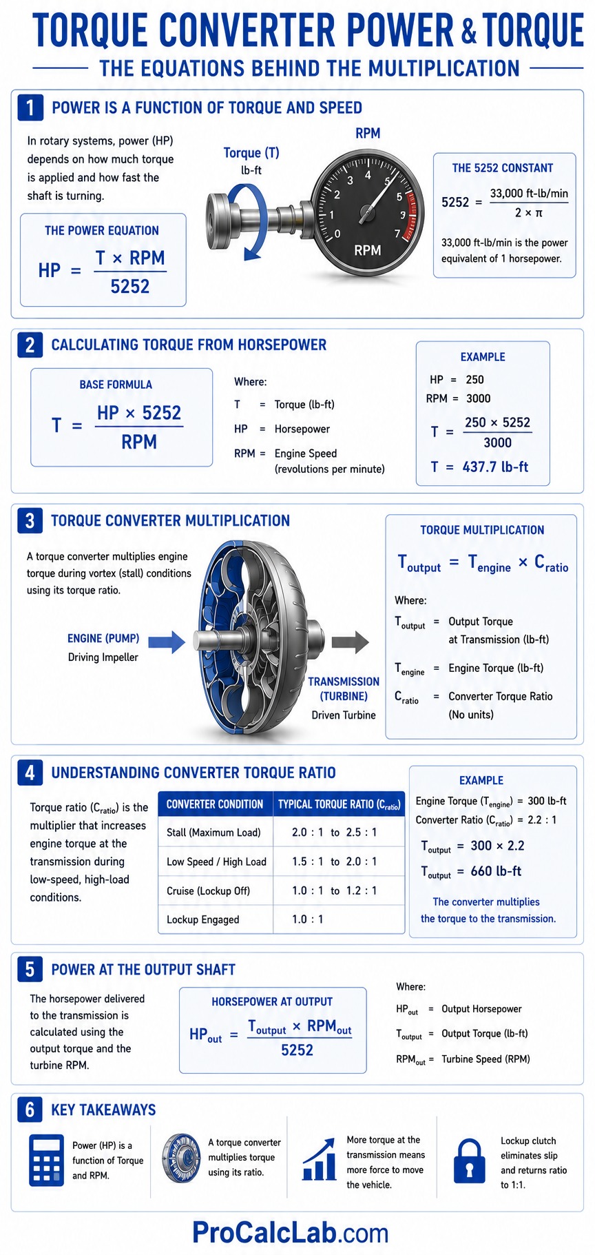
The base formula for calculating torque when horsepower is known is:
T = HP × 5252 / RPM
Where:
- T represents Torque in pound-feet
- HP represents Engine Horsepower
- RPM represents Engine Revolutions Per Minute
When the torque converter is actively multiplying power during vortex flow, we calculate the output shaft torque using the converter’s engineered multiplication ratio.
Toutput = Tengine × Cratio
Step-by-Step Launch Calculation Example
Let us look at a real-world scenario. You are engineering a drag racing vehicle. The engine produces a confirmed 500 lb-ft of torque at 4000 RPM. You have selected a 10-inch racing torque converter with a published stall speed of 4000 RPM and a torque multiplication ratio of 2.2.
Step 1: Determine Input Torque at Stall
Because the stall speed perfectly matches the engine’s peak torque curve, the engine is applying its full 500 lb-ft of torque to the impeller housing the moment the throttle is pinned flat.
Step 2: Apply the Multiplication Ratio
The stator locks down, redirecting the fluid and multiplying the force by a factor of 2.2 before delivering it to the turbine.
Toutput = 500 × 2.2
Toutput = 1100 lb-ft
Step 3: Analyze the Results
While the engine only produces 500 lb-ft of torque, the transmission input shaft experiences a massive twisting force of 1100 lb-ft during the first few feet of the launch. This massive mechanical advantage is exactly why automatic transmission cars consistently launch harder and more predictably off a drag strip starting line than manual transmission cars utilizing a mechanical friction clutch.
Understanding Stall Speed and the K-Factor
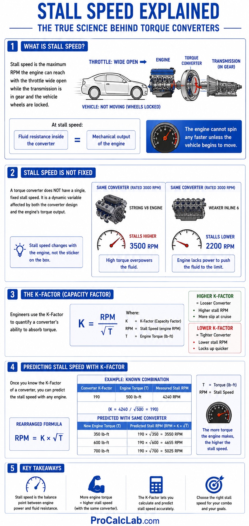
Stall speed is perhaps the most heavily debated topic among automotive builders. Simply put, stall speed is the maximum RPM the engine can reach with the throttle wide open while the transmission is in gear and the vehicle wheels are locked stationary. At this specific RPM, the fluid resistance inside the converter equals the mechanical output of the engine. The engine cannot spin any faster unless the vehicle begins to move.
📊 A common mistake is assuming a torque converter has a single, fixed stall speed built into it at the factory. This is entirely false. Stall speed is a dynamic variable determined by the physical design of the converter combined with the actual torque output of the engine. If you put a converter advertised as having a 3000 RPM stall speed behind a massive V8, it might stall at 3500 RPM because the high torque overpowers the fluid. If you put that exact same converter behind a weak inline 6 engine, it might only stall at 2200 RPM because the engine lacks the power to push the fluid to the designed limit.
Engineers quantify this relationship using a metric called the K-Factor, also known as the Capacity Factor. The K-Factor represents the converter’s ability to absorb torque.
K = RPM / √T
A higher K-Factor indicates a looser torque converter that allows higher engine RPMs before transferring power. A lower K-Factor indicates a tighter converter that grabs the engine quickly at low RPMs. By calculating the K-Factor of a known engine and converter pairing, an engineer can mathematically predict exactly what the stall speed will be if that same converter is bolted to a different engine.
Engineering Data Tables
Selecting the proper torque multiplication ratio and stall speed requires matching the converter to the specific weight, gearing, and camshaft profile of the vehicle. The tables below outline standard industry baselines used during the initial design phase of powertrain development.
Table 1: Typical Torque Multiplication Ratios by Application
| Vehicle Application Type | Typical Torque Ratio | Primary Engineering Goal |
|---|---|---|
| Heavy Duty Diesel Truck | 1.8 to 2.0 | Low heat generation during sustained heavy towing loads. |
| Standard Passenger Car | 1.9 to 2.1 | Smooth engagement and maximized highway fuel economy. |
| Street Performance V8 | 2.2 to 2.4 | Aggressive off-the-line acceleration with moderate heat buildup. |
| Dedicated Drag Racing | 2.4 to 2.6 | Maximum torque multiplication for lowest possible 60-foot times. |
Table 2: Estimated Stall Speeds Based on Camshaft Duration
| Camshaft Duration at 0.050 Lift | Recommended Stall Speed RPM | Idle Quality Characteristics |
|---|---|---|
| Under 210 degrees | 1200 to 1800 RPM | Smooth stock idle with high vacuum. Tight fluid coupling. |
| 210 to 225 degrees | 2000 to 2500 RPM | Slight lope at idle. Requires slightly looser converter to prevent stalling in gear. |
| 225 to 240 degrees | 2800 to 3500 RPM | Aggressive idle. Must slip at low RPM to keep engine in power band. |
| Over 240 degrees | 3800 to 5000+ RPM | Rough racing idle. Low vacuum. Requires highly modified fluid paths. |
Heat, Ballooning, and Practical Troubleshooting
In the field, fluid coupling is highly effective, but it is never 100% efficient due to fluid shear. When turbine blades slash through transmission fluid at high RPMs, they generate immense friction. This friction manifests as thermal energy. Heat is the absolute greatest enemy of an automatic transmission.
Thermal Runaway and Fluid Oxidation
An ideal operating temperature for automatic transmission fluid is 175 degrees Fahrenheit. At this temperature, high-quality fluid can last upwards of 100000 miles. However, when a vehicle is hauling a heavy load up a steep grade, the torque converter experiences continuous slip. The temperature inside the housing can rapidly spike past 250 degrees Fahrenheit. At 250 degrees, the chemical bonds inside the fluid begin to break down, forming hard varnish and sludge. By 300 degrees, the fluid is completely destroyed, internal transmission seals melt, and clutch packs burn up within minutes. This is why heavy-duty applications demand massive aftermarket plate-and-fin fluid coolers mounted in front of the engine radiator.
Torque Converter Ballooning
When high-horsepower racing engines spin a standard torque converter past 6000 RPM, the internal fluid pressure pushes outward against the steel housing with tremendous force. The front face of the converter can physically bow outward, a failure mode known as ballooning. When a converter balloons, it pushes directly against the engine crankshaft, instantly destroying the engine thrust bearings. To prevent this catastrophic failure, high-performance converters feature thick anti-ballooning plates welded directly to the outside of the impeller and turbine housings, providing the structural rigidity necessary to contain extreme hydraulic pressures.
Stator Sprag Failure
A common field diagnosis involves a vehicle that feels incredibly sluggish taking off from a stoplight but drives completely fine once it reaches 30 miles per hour. This is almost always a failed stator sprag clutch. If the 1-way roller clutch breaks, the stator freewheels in both directions. Without a stationary stator to redirect the fluid, the converter loses its ability to multiply torque. It simply acts as a 1 to 1 fluid coupling at all times, making a heavy vehicle feel utterly gutless off the line.
The Lock-Up Clutch: Achieving 100% Efficiency
To meet modern fuel economy standards, engineers had to solve the inherent 5% to 10% fluid slip that occurs even during optimal rotary flow at highway speeds. They solved this by installing a mechanical friction clutch completely inside the fluid housing, known as the Lock-Up Torque Converter Clutch.
💧 The lock-up clutch consists of a friction disc splined to the turbine, positioned just millimeters away from the machined inside cover of the impeller housing. When the vehicle reaches a steady cruising speed on the highway, the powertrain control module commands a solenoid inside the transmission valve body to open. This solenoid routes high-pressure hydraulic fluid directly through the center of the transmission input shaft, flooding the space behind the lock-up clutch piston.
This hydraulic pressure forces the friction material hard against the front cover of the torque converter housing. The turbine is now mechanically locked to the impeller. Fluid dynamics are completely bypassed, and power is transferred mechanically at a perfect 1 to 1 ratio with absolutely 0% slip. Engine RPM drops, fuel economy increases, and internal heat generation is virtually eliminated.
Summary of Engineering Principles
The torque converter is a brilliant piece of hydraulic engineering that solves the massive disconnect between a high-RPM internal combustion engine and a heavy, stationary vehicle chassis. By utilizing centrifugal force, vortex fluid flow, and the mechanical redirection provided by a 1-way stator, the converter successfully acts as an automatic reduction gear exactly when leverage is needed most.

Whether you are designing a heavy equipment hauler or engineering a high-RPM drag racing chassis, selecting the correct stall speed and managing the resulting thermal loads is critical to drivetrain survival. By executing accurate mathematical baselines and understanding the physics of fluid shear, you can harness fluid dynamics to multiply engine power reliably under the harshest mechanical conditions.
Literature
- Society of Automotive Engineers. Design Practices: Passenger Car Automatic Transmissions. SAE International. A comprehensive compilation of white papers detailing fluid dynamics and stator vane angles.
- Gilles, Tim. Automotive Transmissions and Transaxles. Cengage Learning. An in-depth textbook covering planetary gearsets, lock-up clutch hydraulics, and failure mode analysis.
- Robert Bosch GmbH. Bosch Automotive Handbook. Bentley Publishers. The definitive reference manual covering torque capacity factors, heat rejection calculations, and thermal degradation of transmission fluids.

David Parry — Senior Engineering Analyst
Specializing in electronics and physics-based simulations with 20+ years of engineering experience. David ensures the mathematical and physical accuracy of the tools at ProCalcLab.