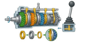
Every engineer or mechanic who has worked on older machinery knows the visceral sound of grinding metal. Before the widespread adoption of synchronizers, shifting gears required precise throttle blipping, double-clutching, and an acute ear for engine speeds. If you missed the RPM match by even a small margin, the unyielding steel teeth would violently clash. Today, modern manual transmissions execute 1000s of shifts flawlessly, masking the incredibly violent kinetic energy exchange happening just inches away from the driver.
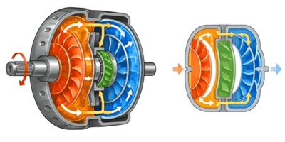

🚚 Understanding how a manual transmission manages this energy is a fundamental rite of passage for mechanical engineers and automotive designers. An internal combustion engine produces usable torque across a very narrow speed range—typically between 1500 and 5000 RPM. Without a gearbox to multiply torque at low speeds and multiply speed at high speeds, a vehicle simply could not accelerate from a dead stop and cruise at highway speeds.
In this guide, we break down the exact mechanical sequence inside a constant mesh gearbox. We will look at the physics of the synchronizer assembly, map out the mathematics of gear ratios and road speeds, and explore the common failure modes we encounter in the field.
Table of Contents
The Anatomy of a Constant Mesh Gearbox
A common mistake when visualizing a transmission is picturing gears sliding up and down a shaft, physically crashing their teeth into one another to engage. While early crash boxes operated this way, modern manual transmissions use a constant mesh design. In a constant mesh gearbox, the gears are always physically interlocked with their mating counterparts. They do not move laterally along the shaft to engage.
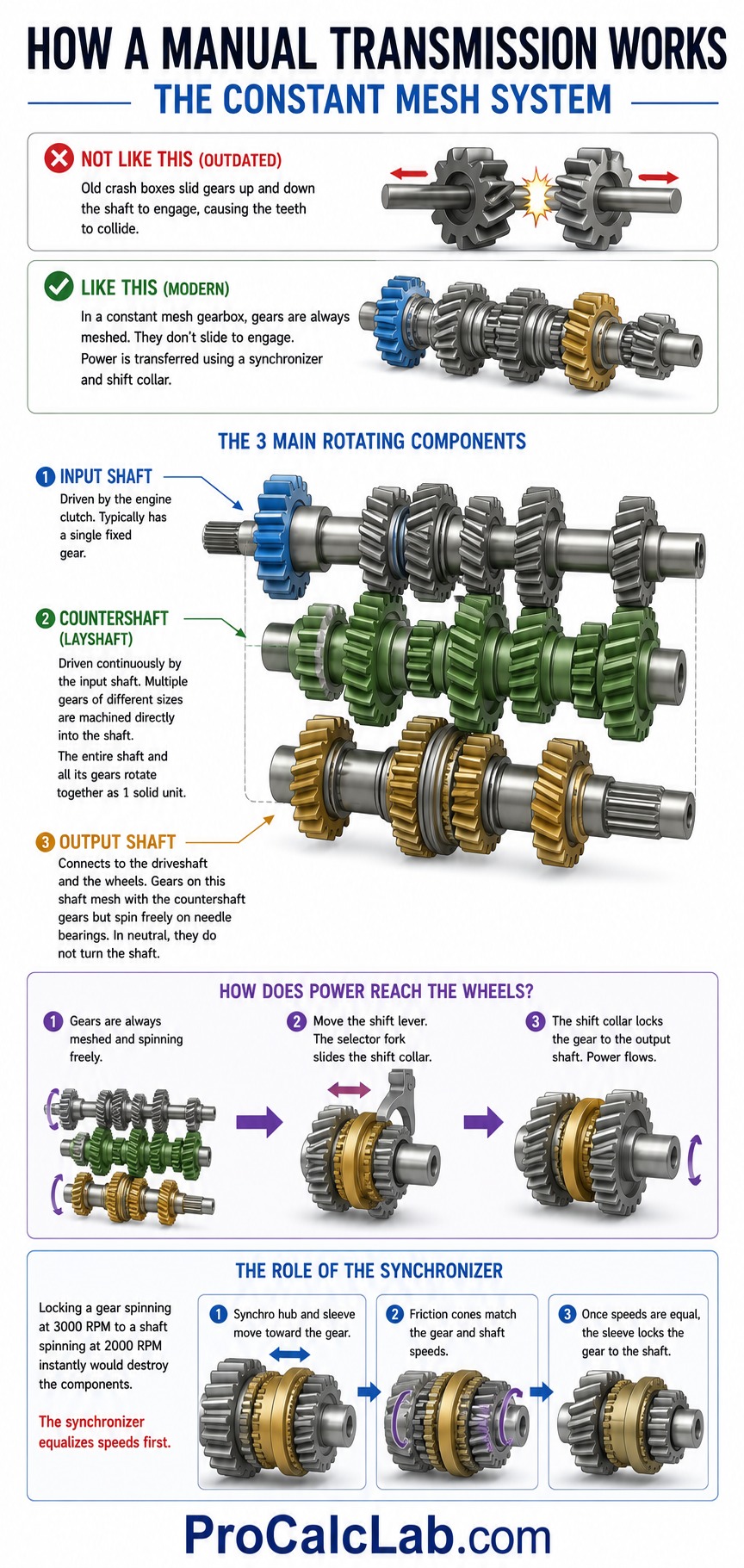
The system relies on 3 primary rotating components:
- The Input Shaft: Driven directly by the engine clutch, this shaft transmits power into the transmission case. It typically features a single fixed drive gear.
- The Countershaft or Layshaft: This shaft is driven continuously by the input shaft. It features multiple gears of varying sizes machined directly into the shaft itself. Therefore, the entire countershaft and all its gears rotate together as 1 solid unit.
- The Output Shaft: This shaft connects to the driveshaft and ultimately the wheels. The gears on this shaft mesh continuously with the countershaft gears. However, these output gears ride on needle bearings. When neutral is selected, these gears spin completely freely around the output shaft without turning it.
If the gears are always meshed and freely spinning, how does power actually reach the wheels? The answer lies in the shift collar and the synchronizer assembly. To engage a gear, the driver moves the shift lever, which pushes a selector fork. This fork slides a splined collar along the output shaft. The collar locks the freely spinning gear to the output shaft, allowing power to flow. Locking a gear spinning at 3000 RPM to a shaft spinning at 2000 RPM instantly would destroy the components. We need a mechanism to equalize their speeds first.
The Magic of the Synchronizer Assembly
The synchronizer, or synchromesh, is arguably the most brilliant mechanical solution in modern automotive engineering. Its sole purpose is to use mechanical friction to match the rotational speed of the freewheeling gear to the rotational speed of the output shaft before the locking teeth engage.
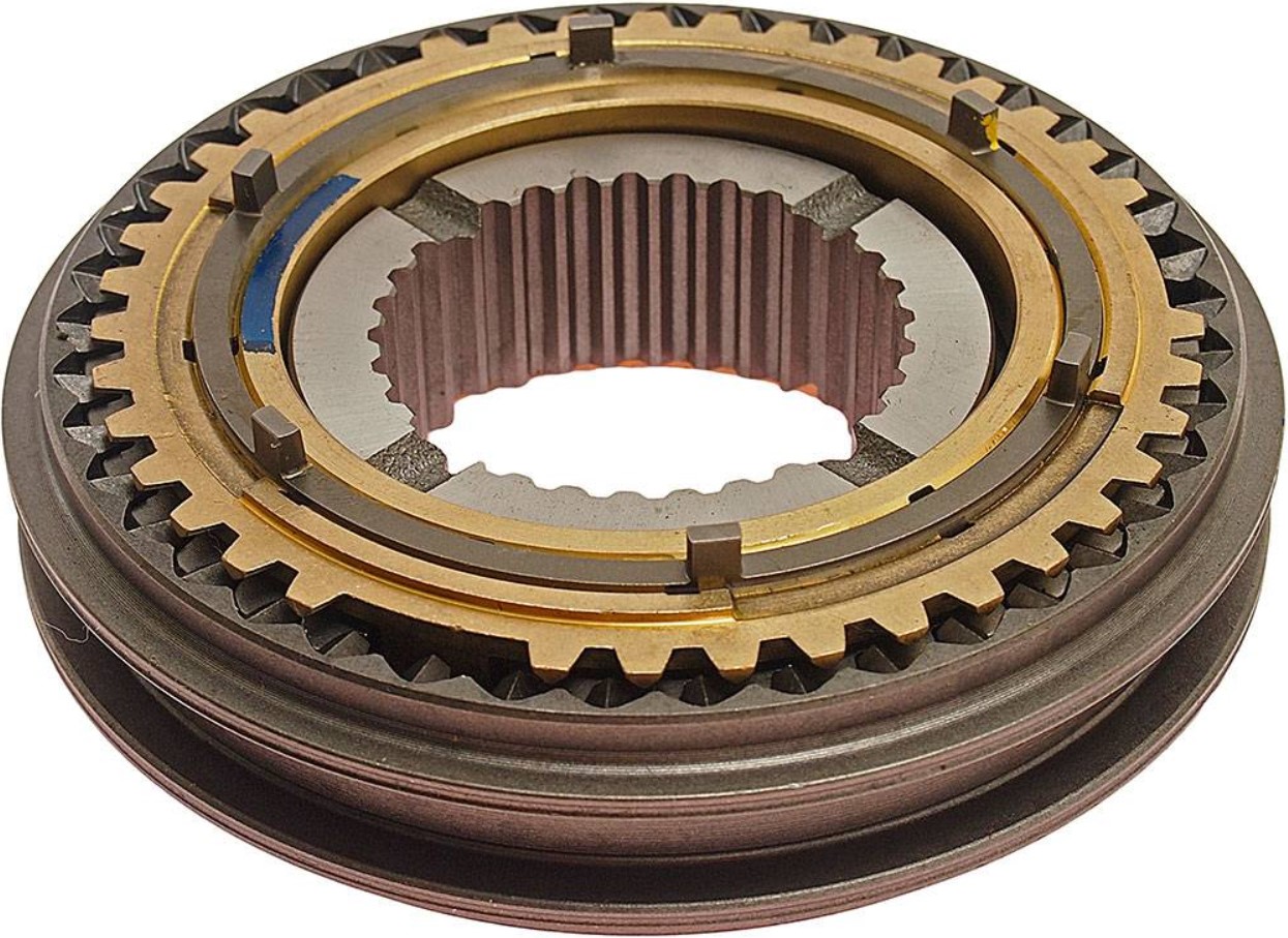
A complete synchronizer assembly consists of 3 main parts: the hub, the sleeve, and the blocker ring. The hub is splined directly to the output shaft and rotates with it. The sleeve slides back and forth over the hub, pushed by the shift fork. The blocker ring, often called a baulk ring, sits between the hub and the gear itself.
When you initiate a shift, the sequence unfolds in 3 distinct stages:
- Selection and Friction: As the shift fork pushes the sleeve toward the target gear, the sleeve pushes the blocker ring against a conical shoulder machined onto the side of the gear. This creates a friction cone clutch.
- Speed Equalization: The blocker ring is typically made of a softer material like brass, or lined with carbon fiber, to maximize friction. As it presses against the steel cone of the gear, the friction acts as a miniature brake or accelerator. It forces the freely spinning gear to speed up or slow down until its RPM exactly matches the output shaft RPM.
- Locking Engagement: Only when the speeds are 100% equal will the blocker ring rotate slightly, aligning its outer teeth with the splines on the sleeve. The sleeve then glides seamlessly over the blocker ring and engages the dog teeth on the side of the gear. The gear is now mechanically locked to the shaft.
From a practical standpoint, this entire process happens in a fraction of a second. If you try to force the shifter into gear too quickly, you defeat the blocker ring. The sleeve attempts to engage the dog teeth while a speed differential still exists, resulting in the dreaded grinding noise. You are actually hearing the dog teeth clashing, not the main helical gear teeth.
The Mathematics of Gear Ratios and Vehicle Speed
✍ Engineers must calculate the exact vehicle speed resulting from a specific engine RPM and gear selection. This dictates whether a car will have aggressive acceleration or efficient highway cruising capability. The total mechanical advantage is a product of the transmission gear ratio multiplied by the final drive ratio located in the differential.
To calculate the theoretical velocity of a vehicle, we use a standard formula that incorporates engine speed, gear reduction, and tire circumference. For the US market, this formula uses a constant of 336 to convert inches and minutes into miles per hour.
The Imperial Velocity Formula
V = (RPM × D) / (Rgear × Rfinal × 336)
Here is what each variable represents:
- V: Vehicle speed in miles per hour.
- RPM: Engine speed in revolutions per minute.
- D: Total overall diameter of the driven tire in inches.
- Rgear: The specific gear ratio of the transmission for the selected gear.
- Rfinal: The final drive ratio of the differential.
- 336: A mathematical constant that resolves the conversion from inches per minute to miles per hour.
Let us walk through a concrete, real-life calculation. We are designing a sports car and want to know its top speed in 3rd gear at redline. The engine redlines at 7000 RPM. We are running a 26 inch diameter rear tire. Our 3rd gear ratio is 1.30 to 1, and our rear differential has a final drive ratio of 3.73 to 1.
First, we multiply the engine speed by the tire diameter. 7000 multiplied by 26 equals 182000.
Next, we calculate our total driveline reduction by multiplying the transmission ratio, the final drive, and our constant. 1.30 multiplied by 3.73 multiplied by 336 equals 1629.26.
Finally, we divide the top number by the bottom number. 182000 divided by 1629.26 gives us exactly 111.7 miles per hour.
The Metric Velocity Formula
For international engineering projects, we adapt the formula to use millimeters for tire diameter and output the velocity in kilometers per hour. The underlying physics remain identical, but the mathematical constant changes to 5306 to accommodate the metric unit conversions.
V = (RPM × D) / (Rgear × Rfinal × 5306)
Typical Transmission Ratios
⚙ To provide a clear picture of how torque multiplication shifts across a standard gearbox, we can look at a typical 5-speed manual transmission configuration. First gear offers massive torque multiplication for launching the vehicle, while fifth gear acts as an overdrive unit for fuel economy.
The following table illustrates typical ratios for a passenger car transmission and the resulting overall driveline ratio when paired with a 3.50 final drive.
| Gear Selection | Transmission Ratio | Total Driveline Ratio |
|---|---|---|
| 1st Gear | 3.16 : 1 | 11.06 : 1 |
| 2nd Gear | 1.88 : 1 | 6.58 : 1 |
| 3rd Gear | 1.30 : 1 | 4.55 : 1 |
| 4th Gear (Direct) | 1.00 : 1 | 3.50 : 1 |
| 5th Gear (Overdrive) | 0.79 : 1 | 2.76 : 1 |
Notice that 4th gear provides a 1.00 to 1 ratio. In many transmission designs, 4th gear physically locks the input shaft directly to the output shaft. Power flows straight through the gearbox without routing through the countershaft. This provides 100% transmission efficiency with zero parasitic loss from gear meshing.
Practical Application and Field Troubleshooting
In the field, we often see manual transmissions suffer from specific, highly predictable wear patterns. Because the driver introduces a massive human element into the kinetic system, component lifespan varies wildly. Understanding the mechanical theory allows us to diagnose problems based on tactile feedback from the shift lever.
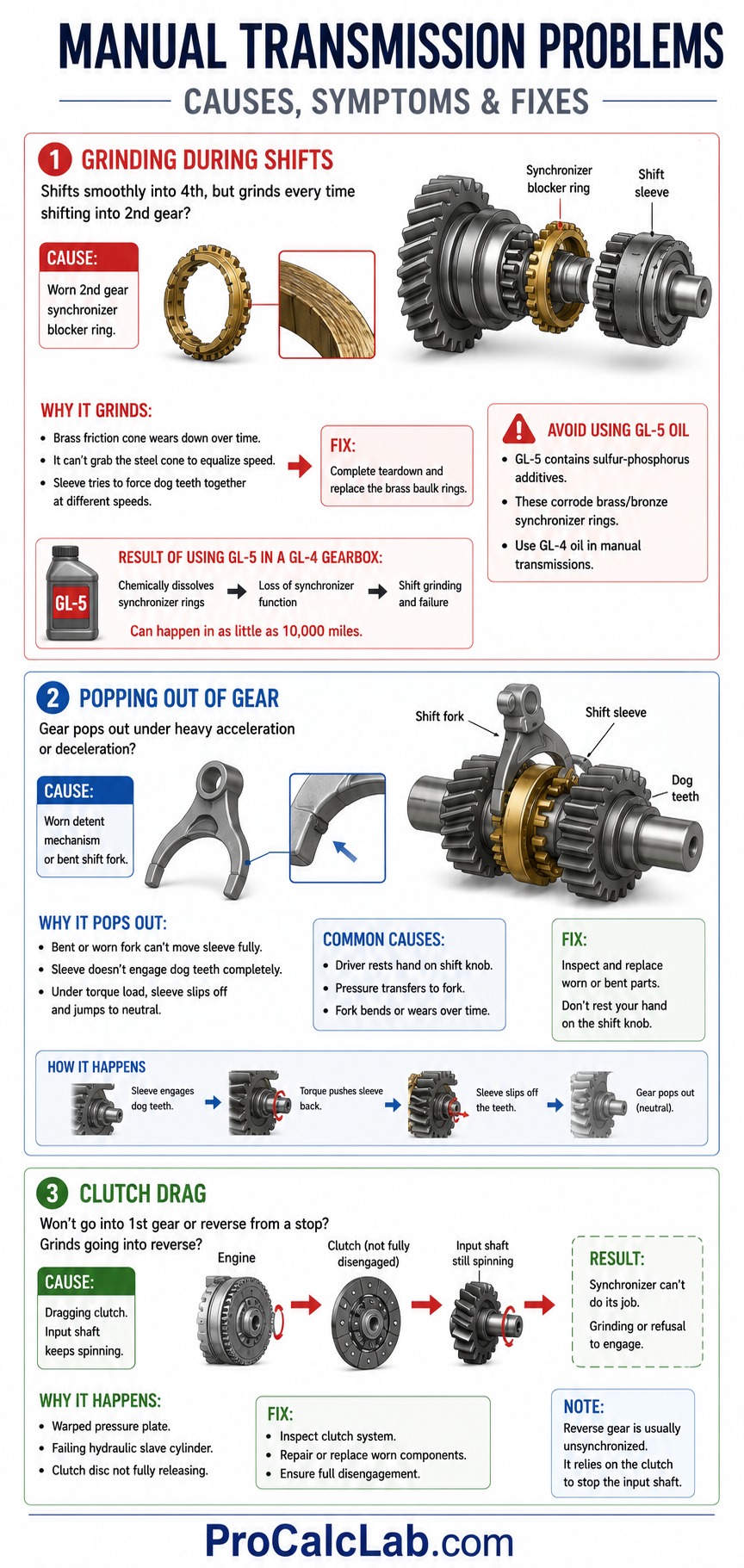
Grinding During Shifts
If a transmission shifts smoothly into 4th gear but grinds every time you shift into 2nd gear, the main helical gears are completely fine. The grinding indicates a failure of the 2nd gear synchronizer blocker ring. Over 100,000 miles of shifting, the brass friction cone wears down. It loses its ability to grab the steel cone on the gear and equalize the speed. Consequently, the shift sleeve attempts to ram the dog teeth together while they are spinning at different speeds. The only fix is a complete teardown and replacement of the brass baulk rings.
A common mistake we see among DIYers is filling an older manual transmission with modern GL-5 specification gear oil. GL-5 contains high levels of sulfur-phosphorus extreme pressure additives. While great for steel differential gears, these additives actively corrode yellow metals like brass and bronze at high temperatures. Pumping GL-5 into a gearbox designed for GL-4 will chemically dissolve the synchronizer rings within 10,000 miles, leading to complete shift failure.
Popping Out of Gear
Another frequent issue is a transmission that pops out of gear under heavy acceleration or deceleration. The shift sleeve engages the dog teeth, but engine torque pushes it back into neutral. This is rarely a gear failure. It almost always points to a worn detent mechanism or a bent shift fork.
The shift fork rides in a groove machined into the outside of the shift collar. If a driver rests their hand heavily on the shift knob while driving, that pressure transfers directly to the shift fork inside the spinning gearbox. Over time, the fork bends or wears down. When the driver attempts to shift, the bent fork cannot push the sleeve far enough onto the dog teeth to fully engage. Under heavy torque load, the sleeve simply slips off the edge of the teeth and pops into neutral.
Clutch Drag
Sometimes a transmission will refuse to go into 1st gear or reverse from a dead stop. Reverse gear is typically unsynchronized to save cost and space. If the transmission grinds going into reverse, it means the input shaft is still spinning. This points to a dragging clutch. Even with the clutch pedal fully depressed, a warped pressure plate or a failing hydraulic slave cylinder fails to fully separate the friction disc from the flywheel. The engine continues feeding a small percentage of torque into the input shaft, completely defeating the synchronizer logic.
Summary and Engineering Next Steps
📊 The modern manual transmission is a masterpiece of kinetic energy management. It uses constant mesh helical gears to ensure quiet operation and robust power delivery, while relying on the elegant friction physics of the synchronizer assembly to allow seamless shifting. By understanding the mathematics behind gear reduction, you can perfectly tailor a vehicle drivetrain for maximum launch torque or optimal fuel efficiency.
Mastering these concepts requires an intuition for how RPM, load, and gear ratios interact in real time. Reading about torque multiplication is 1 thing, but experiencing how an engine bogs down in the wrong gear or bounces off the rev limiter requires practice. To bridge the gap between mechanical theory and driver execution, we highly recommend utilizing our car driving training simulator. It allows you to visualize the exact relationship between throttle input, clutch engagement, and internal gear ratios in a risk-free, highly accurate physical model. You can experiment with different shift points and instantly observe how the torque curve affects forward velocity.
Literature
- Budynas, R. G., and Nisbett, J. K. Shigley’s Mechanical Engineering Design. McGraw-Hill Education. A foundational text detailing the stress analysis of helical gears and shaft deflection.
- Bosch, R. Bosch Automotive Handbook. Bentley Publishers. The definitive industry reference for drivetrain calculations, synchronizer friction coefficients, and automotive kinematics.
- Erjavec, J. Manual Transmissions and Transaxles. Cengage Learning. A highly practical guide focusing on the teardown, inspection, and diagnosis of synchronizer and shift fork failures.

David Parry — Senior Engineering Analyst
Specializing in electronics and physics-based simulations with 20+ years of engineering experience. David ensures the mathematical and physical accuracy of the tools at ProCalcLab.