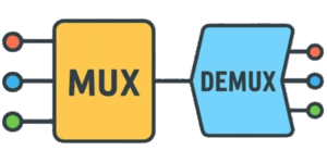

This tool helps you analyze multiplexers and demultiplexers quickly. It calculates key parameters, generates an address map and runs a live animation that cycles through channels so you can see switching behavior at the specified signal rate.


What a MUX and DEMUX do
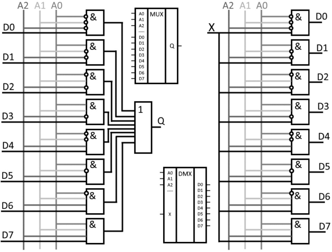
- Multiplexer (MUX) — selects one of several input channels and forwards it to a single output using address lines.
- Demultiplexer (DEMUX) — takes one input and routes it to one of many outputs determined by control signals.
Key features
- Switch between MUX and DEMUX modes with a single click and update the diagram automatically.
- Configure channel count, data bit width, signal frequency, switching delay, supply voltage and load resistance.
- Automatic calculation of address/control lines (ceil(log2(N))), data throughput (bits × frequency) and theoretical maximum operating frequency based on delay.
- Estimate load current and electrical power for the selected load and supply voltage.
- Auto-generated address table for every channel and a step-through animation showing active channel selection.
How to use
- Select the operating mode: MUX or DEMUX.
- Enter the number of channels (examples: 6, 12, 24), the signal bit width, and the desired signal frequency in MHz.
- Set the switching delay in nanoseconds, supply voltage, and load resistance.
- Press Calculate to display results and start the animation that cycles channels according to the frequency you entered.
Interpreting results
- Address lines — minimum control inputs required: ceil(log2(N)).
- Throughput — raw data rate in bits per second (bit width × frequency).
- Max. frequency (theory) — approximate upper bound based on switching delay: 1 / (2 × delay).
- Load current — estimated I = V / R.
- Power — estimated P = V × I (useful for thermal and supply planning).

Quick comparison
| Parameter | Multiplexer | Demultiplexer |
|---|---|---|
| Purpose | Combine many inputs into one output | Distribute one input to many outputs |
| Control lines | Select which input is routed | Select which output receives the signal |
| I/O count | N inputs, 1 output | 1 input, N outputs |
| Typical use | Data bus steering, ADC input selection | Address decoding, signal routing |
Multiplexers and demultiplexers are widely used in embedded systems, instrumentation and digital logic. Use them to expand input/output lines on microcontrollers, build time-division multiplexed data buses, and route signals in test setups or communication front-ends.
Example
Suppose you select 12 channels, 2-bit data, 4.5 MHz signal, 30 ns switching delay, 3.3 V supply and a 330 Ω load. The tool will report:
- Address lines = ceil(log2(12)) = 4
- Throughput = 2 bits × 4.5 MHz = 9 Mbps
- Max theoretical freq ≈ 1 / (2 × 30 ns) ≈ 16.67 MHz
- Load current ≈ 3.3 / 330 ≈ 10 mA
- Power ≈ 3.3 × 0.01 ≈ 33 mW
For reliable operation keep switching frequency well below the theoretical maximum to allow for propagation delays and signal settling. Account for driver strength and bus capacitance when estimating real-world switching limits. When designing for many channels, consider hierarchical multiplexing to simplify address logic and reduce routing complexity.
Recommended reading
- “Digital Design and Computer Architecture” — David Harris & Sarah Harris
- “CMOS VLSI Design: A Circuits and Systems Perspective” — Neil Weste & David Harris
- “The Art of Electronics” — Paul Horowitz & Winfield Hill
- “Digital Logic and Microprocessor Design with VHDL” — Enoch O. Hwang

David Parry — Senior Engineering Analyst
Specializing in electronics and physics-based simulations with 20+ years of engineering experience. David ensures the mathematical and physical accuracy of the tools at ProCalcLab.