
In the field, we often see technicians treat roller chains exactly like drive belts. They assume a chain provides smooth, continuous power transmission across rotating shafts. This is a critical engineering fallacy. A belt wraps around a perfectly circular sheave, creating a constant radius of engagement. A roller chain wraps around a sprocket, which is fundamentally a polygon. As the chain links engage the teeth of this polygon, the effective driving radius constantly changes. This creates a mechanical pulsing effect that introduces severe shock loads into the drivetrain at high speeds.
Understanding the interaction between a rigid steel chain and a toothed sprocket is the absolute foundation of mechanical power transmission design. This article breaks down the anatomy of roller links, details the physics of polygonal action, provides the exact mathematics for sizing your drive, and outlines practical troubleshooting techniques to keep your machinery running smoothly under extreme loads.
Table of Contents
The Anatomy of a Roller Chain
To grasp how a chain drive distributes force, you must first understand its internal architecture. A standard roller chain is not a single flexible band. It is a highly complex series of precision plain bearings linked together. A typical drive chain consists of alternating outer links and inner links, built from 5 distinct mechanical components.
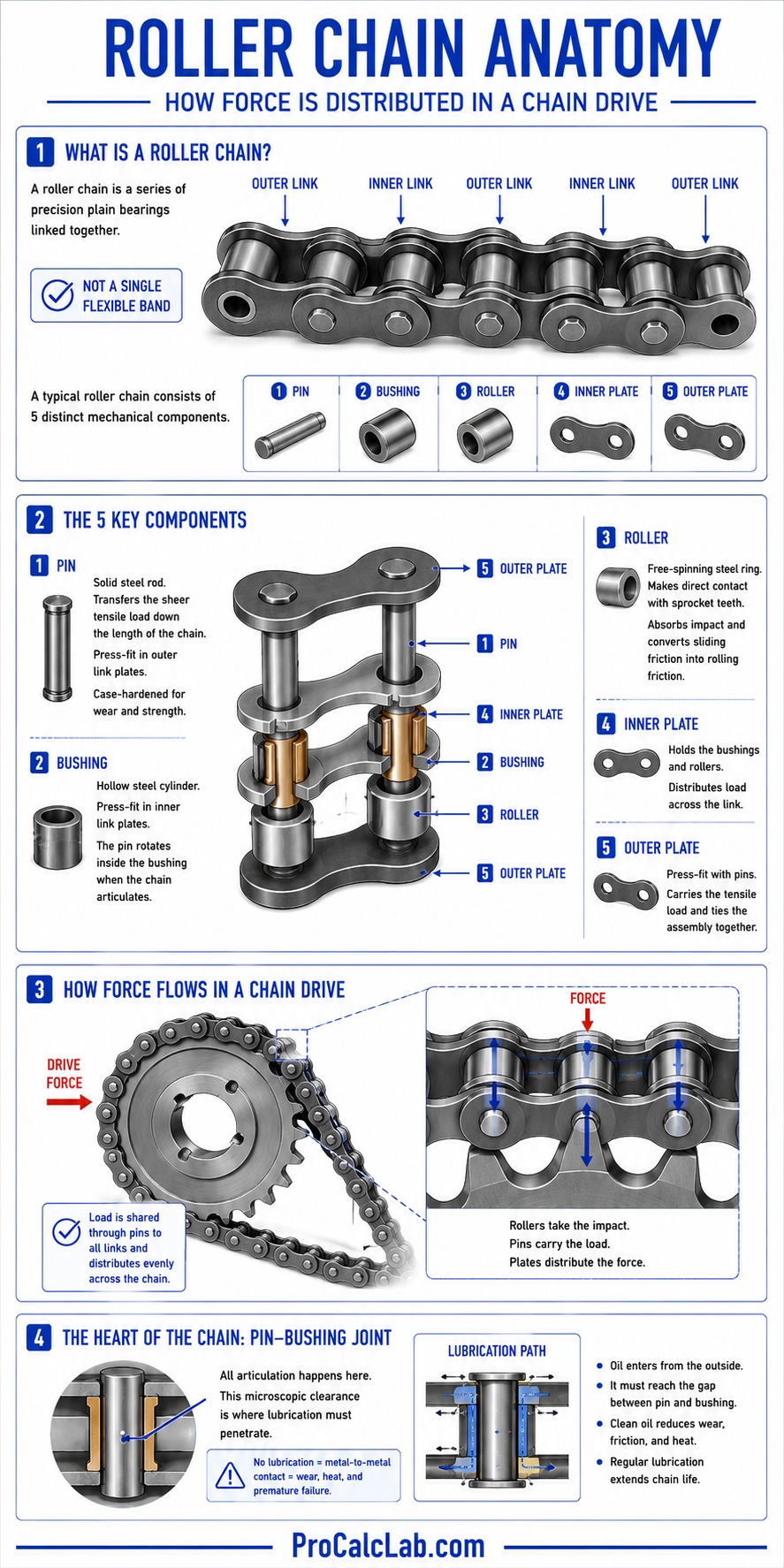
The foundation of the chain is the pin. The pin is a solid steel rod that transfers the sheer tensile load down the length of the chain. These pins are press-fit tightly into the outer link plates. Because the pins must survive constant shearing forces and abrasive wear, they are typically cold-drawn and case-hardened.
Riding directly over the pin is the bushing. The bushing is a hollow steel cylinder press-fit into the inner link plates. When the chain bends around a sprocket, the pin rotates inside this bushing. This pin-bushing joint is the true heart of the chain. All articulation happens right here, meaning this microscopic clearance zone is where all lubrication must ultimately penetrate. If oil fails to reach the gap between the pin and the bushing, the steel surfaces gall, overheat, and rapidly destroy the chain.
Surrounding the bushing is the roller. The roller is a free-spinning steel ring that makes direct physical contact with the sprocket teeth. When a chain engages a sprocket, the roller absorbs the initial impact force. Because it is free to rotate, it transforms what would be brutal sliding friction into manageable rolling friction as the link seats itself into the root of the sprocket tooth. Finally, the inner and outer plates tie the entire assembly together, distributing the massive tensile loads evenly across the drive system.
The Physics of Polygonal Action
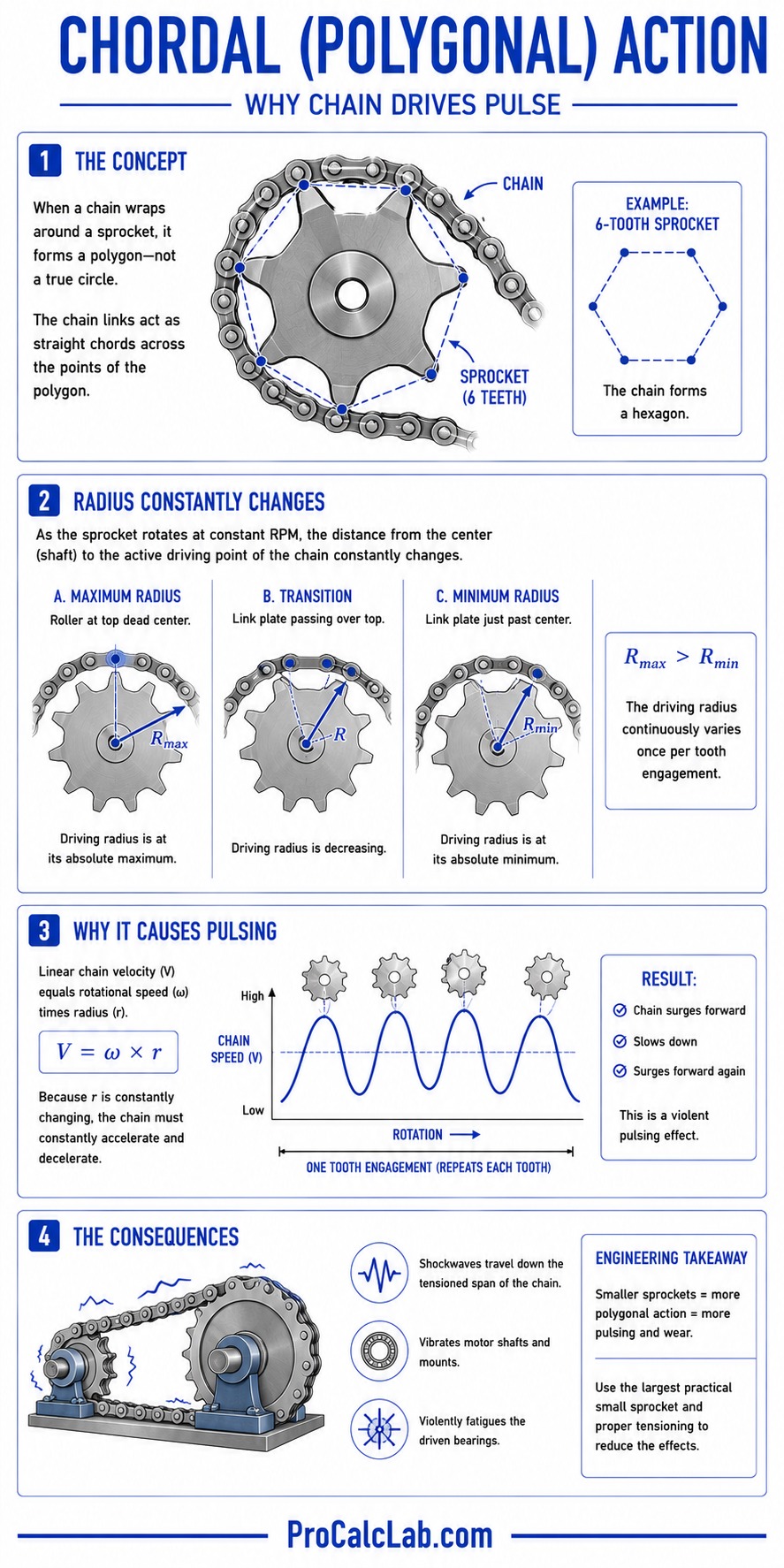
The most critical concept in chain drive engineering is chordal action, frequently referred to as polygonal action. When a chain wraps around a sprocket, it forms a polygon rather than a true circle. The chain links act as straight chords stretching across the points of the polygon.
✍ Imagine a very small sprocket with exactly 6 teeth. When you wrap a chain around it, the chain forms a hexagon. As this hexagonal sprocket rotates at a constant RPM, the physical distance from the center of the shaft to the active driving point of the chain constantly changes. When the roller is seated directly at the top dead center of the sprocket, the driving radius is at its absolute maximum. As the sprocket rotates and the straight link plate passes over the top, the driving radius drops to its absolute minimum.
Because the linear velocity of the chain equals the rotational speed multiplied by the radius, this constantly changing radius forces the chain to accelerate and decelerate with every single tooth engagement. This is not a smooth process. It creates a violent pulsing effect. The chain surges forward, slows down, and surges forward again. This surging sends a shockwave down the tensioned span of the chain, vibrating the motor shafts and violently fatiguing the driven bearings.
The severity of this chordal action is determined entirely by the number of teeth on the driving sprocket. A 10-tooth sprocket produces a massive speed variation of roughly 5%. A 21-tooth sprocket drops this variation to less than 1%. For high-speed industrial applications, engineering standards dictate that a driving sprocket must have an absolute minimum of 17 teeth. Using fewer than 17 teeth is only acceptable for very low-speed manual operations like hand-cranked winches or slow conveyor lifts. The maintenance crew in my earlier story destroyed their gearbox because they spun a 10-tooth sprocket at 1750 RPM, subjecting their bearings to 17500 violent shock loads every single minute.
Digital Prototyping and Interface Constraints
💻 Because visualizing chordal action and geometric clearances is difficult on paper, modern engineers rely heavily on digital modeling before cutting any metal. We frequently use utilities like our 3D chain drive designer to visually verify sprocket engagement and clearance zones. However, developing effective engineering tools for web platforms requires strict adherence to interface and rendering rules.
When simulating mechanical systems using WebGL or dynamic SVG graphics, developers must perfectly manage the mathematical winding order of the polygon paths representing the sprocket teeth. I have seen poorly coded simulations where automated fill colors jump abruptly or switch entirely when the 3D representation aligns to a flat orientation. This geometric artifact occurs because the mathematical surface normal vector flips across the zero axis, causing the browser to render the inside face of the sprocket as the outside face. By strictly enforcing a persistent vertex winding logic, the mechanical geometry remains stable regardless of the viewing angle.
The Mathematics of Pitch and Center Distance
To design a functional drive, you must calculate the exact length of chain required to connect your driving and driven sprockets at a specific center distance. We measure chain length in pitches rather than raw inches or millimeters. One pitch is the exact center-to-center distance between 2 adjacent pins.
⚙ Using an odd number of pitches forces you to use an offset link, commonly called a half-link. Offset links feature bent plates that combine an inner and outer link into a single unit. Because the plates are bent, they are structurally compromised, instantly reducing the tensile capacity of your entire drive by roughly 30%. From a practical standpoint, you must always round your chain length calculations to the nearest even whole number to avoid offset links entirely.
To calculate the required chain length, we use a standard kinematic equation. Let us define the variables first:
- L: Total chain length measured in pitches.
- C: Center distance between the 2 shafts measured in pitches.
- N: Number of teeth on the large driven sprocket.
- n: Number of teeth on the small driving sprocket.
The standard equation is:
L = 2 * C + (N + n) / 2 + (N – n)2 / (39.48 * C)
Let us walk through a concrete calculation for an agricultural auger drive. We have a center distance of exactly 40 pitches. Our driving motor has a 15-tooth sprocket. Our driven auger shaft requires a massive 60-tooth sprocket to achieve the necessary torque reduction.
First, we solve the center distance multiplier.
2 * 40 = 80 pitches.
Next, we calculate the average number of teeth wrapping the sprockets.
(60 + 15) / 2 = 37.5 pitches.
Now, we solve the final geometric factor representing the angle of the chain span. We subtract the small sprocket teeth from the large sprocket teeth and square the result.
60 – 15 = 45
45 * 45 = 2025
We divide that by our constant multiplied by the center distance.
39.48 * 40 = 1579.2
2025 / 1579.2 = 1.28 pitches.
Finally, we sum the 3 parts together.
L = 80 + 37.5 + 1.28
L = 118.78 pitches.
You cannot purchase 0.78 of a link. If we round down to 118, the chain will be too short to fit over the sprockets. We must round up. To completely avoid a weak offset half-link, we must round up to the next even integer. The required chain length is exactly 120 pitches. We will then slightly increase the physical center distance of the motor mounts to pull the 1.22 pitches of slack out of the system.
Standard Chain Dimensions and Ratings
📝 In the United States, roller chains follow the strict dimensional standards outlined by the American National Standards Institute. The ANSI numbering system is highly logical once you understand the code. The right-hand digit dictates the chain style, where 0 indicates a standard roller chain. The left-hand digits indicate the pitch measured in eighths of an inch. Therefore, an ANSI 60 chain has a pitch of 6/8 of an inch, which simplifies to 3/4 of an inch.
The following table outlines the physical dimensions and minimum tensile breaking strengths of the most common industrial sizes. The data is presented with both Metric and Imperial values separated cleanly by a slash to avoid conversion errors when sourcing components internationally.
| ANSI Size | Pitch [mm / in] | Roller Diameter [mm / in] | Tensile Strength [kN / lbf] |
|---|---|---|---|
| 40 | 12.7 / 0.5 | 7.9 / 0.31 | 13.8 / 3125 |
| 50 | 15.8 / 0.62 | 10.1 / 0.4 | 21.8 / 4880 |
| 60 | 19.0 / 0.75 | 11.9 / 0.46 | 31.3 / 7030 |
| 80 | 25.4 / 1 | 15.8 / 0.62 | 55.6 / 12500 |
| 100 | 31.7 / 1.25 | 19.0 / 0.75 | 87.0 / 19560 |
Practical Field Troubleshooting
Even a perfectly engineered drive system will fail prematurely if maintenance teams do not understand the mechanics of wear and tensioning. When troubleshooting heavy machinery, you must look beyond obvious symptoms and address the root mechanical cause.
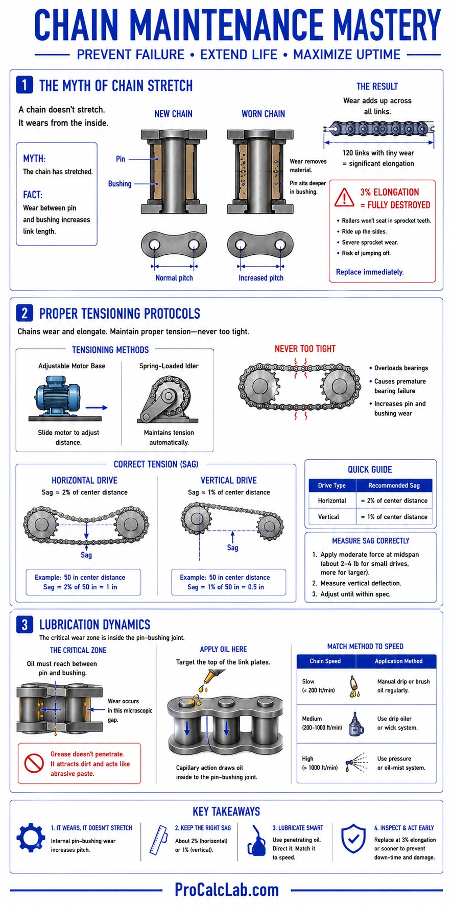
The Myth of Chain Stretch
A common mistake during routine inspections is assuming that an elongated chain has physically stretched. Mechanics frequently report that the steel side plates have yielded under heavy torque. This is completely false. A properly designed drive operates well below the yield strength of the steel. The chain is not stretching. It is wearing out from the inside.
As the chain articulates under load, the case-hardened pin continuously grinds against the inside of the bushing. If lubrication is inadequate, this friction slowly removes microscopic layers of steel from both components. As material is lost, the pin sits deeper inside the bushing. This increases the center-to-center distance of every single link by a tiny fraction of a millimeter. When you multiply this microscopic wear across 120 individual links, the entire chain becomes visibly longer. By the time a chain has elongated by 3%, the pitch has changed so drastically that the rollers will no longer seat properly in the bottom of the sprocket teeth. They will ride up the sides of the teeth, severely wearing the sprocket and eventually jumping off entirely. A chain with 3% elongation is fully destroyed and must be replaced immediately.
Proper Tensioning Protocols
Because chains inevitably wear and elongate, the drive must feature an adjustable tensioning mechanism. Usually, this involves sliding the motor base away from the driven shaft or installing a spring-loaded idler sprocket on the slack side of the chain span.
You must never pull a roller chain perfectly tight like a guitar string. A completely rigid chain drastically increases the radial load on the shaft bearings, causing premature bearing failure and excessive pin wear. Instead, you must leave a calculated amount of sag in the slack span of the chain. For standard horizontal drives, the slack side should sag vertically by roughly 2% of the total center distance. For example, if your sprockets are 50 inches apart, the chain should have exactly 1 inch of vertical play midway between the sprockets. If the drive is mounted vertically with one sprocket directly above the other, gravity provides no natural sag, and the tension must be kept tighter, usually around 1% of the center distance.
Lubrication Dynamics
Applying heavy grease to the outside of a roller chain is a waste of time and material. As established earlier, the critical wear zone is entirely internal, located in the microscopic gap between the pin and the bushing. Grease is far too thick to penetrate this joint. Furthermore, sticky grease acts as a magnet for abrasive dirt and silica sand, grinding the sprockets into dust.

You must use a lightweight penetrating oil. The oil must be directed precisely onto the top edges of the link plates so capillary action can pull the fluid inward toward the pin. The method of application is dictated strictly by the chain velocity.
- Manual or Drip Lubrication: Used for low-speed drives under 500 feet per minute. Oil is dripped directly onto the link edges via a gravity feed cup.
- Oil Bath Lubrication: Used for medium-speed drives between 500 and 1500 feet per minute. The chain runs inside a sealed casing where the lowest part of the chain dips directly into a shallow pool of oil. If the pool is too deep, the chain will churn the oil excessively, generating massive amounts of heat.
- Oil Stream Lubrication: Required for high-speed drives exceeding 1500 feet per minute. A mechanical pump sprays a continuous, pressurized stream of cooled oil directly onto the inner face of the chain right before it engages the drive sprocket. This lubricates the joints and carries away the immense heat generated by the rapid articulation.
Summary
Roller chains remain one of the most efficient, durable, and reliable methods of mechanical power transmission ever invented. However, they demand strict respect for geometric principles. You must select driving sprockets large enough to minimize the violent shock loads caused by polygonal action. You must calculate pitch lengths perfectly to avoid introducing weak offset links into your driveline. Finally, you must educate your maintenance teams on the internal mechanics of pin wear and capillary lubrication to ensure maximum operational lifespan. When you apply robust mathematical theory alongside proper field maintenance, your chain drives will easily outlast the machines they power.
Literature
- American Chain Association: Standard Handbook of Chains: Design and Applications. The absolute definitive guide covering every aspect of fatigue strength calculation, sprocket geometry, and heavy industrial tensioning standards.
- Shigley, J. E., Mischke, C. R.: Mechanical Engineering Design. A highly detailed university text that thoroughly breaks down the kinematics of chordal action and the dynamic shock loading of transmission components.
- Oberg, E., Jones, F. D.: Machinery’s Handbook. The universal shop-floor reference providing exhaustive tables on ANSI dimensional tolerances, center distance formulas, and required lubrication viscosities.

David Parry — Senior Engineering Analyst
Specializing in electronics and physics-based simulations with 20+ years of engineering experience. David ensures the mathematical and physical accuracy of the tools at ProCalcLab.