
Imagine standing on the catwalk of a 3-megawatt wind turbine nacelle, 300 feet in the air. You can feel the deep, rhythmic vibration of the main planetary gearbox through the steel floor grating. At that scale, mechanical efficiency is not just a marketing specification printed on a datasheet. It is a critical thermal and structural boundary condition. If a 3-megawatt gearbox operates at 96% efficiency, it is losing 4% of its input power. That 4% equates to 120 kilowatts of pure thermal energy being dumped directly into the lubricating oil. If the engineering team miscalculated that efficiency drop, the cooling system will fail to keep up, the synthetic oil will coke, the planet bearings will seize, and the gearbox will tear itself apart.


In the field, we often see junior engineers treat gearboxes as simple black boxes where torque goes in and multiplied torque comes out. They rely on generic efficiency estimates provided by sales representatives. However, when designing heavy industrial machinery, robotics, or high-performance automotive drivetrains, you must understand exactly how and why power is lost inside an epicyclic system. A planetary gearbox does not behave like a standard parallel shaft gear train. The kinematics are infinitely more complex, and the way power flows through the meshing teeth actually works to your advantage.
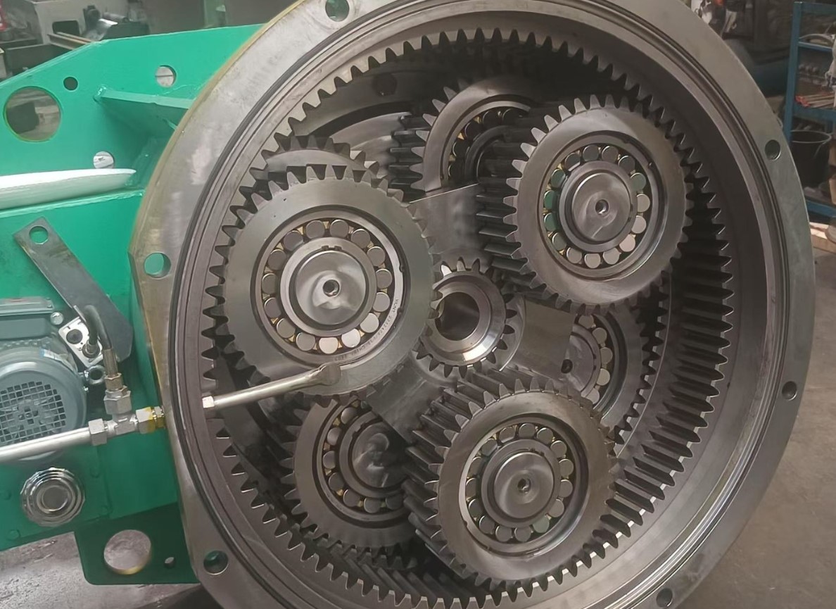
This comprehensive guide will break down the underlying mechanics of epicyclic gear trains. We will explore the phenomenon of coupling power, walk through exact step-by-step mathematical formulas to calculate mechanical efficiency, and outline the practical troubleshooting steps required to manage parasitic field losses like oil churning and bearing drag.
Table of Contents
The Core Mechanics of Planetary Load Distribution
Before we calculate power losses, we must understand how a planetary gearbox distributes physical loads. A standard epicyclic gear set consists of 4 primary components. The sun gear sits directly in the center. Multiple planet gears surround and mesh with the sun gear. The ring gear is an internal gear that encapsulates the planets. Finally, the carrier is a rigid structural arm that connects the center points of all the planet gears together.
📊 A common mistake during calculations is assuming a planetary gearbox suffers the same efficiency penalties as a multi-stage parallel shaft gearbox. In a traditional parallel shaft setup, a single gear tooth takes 100% of the transmitted load at any given moment. To handle massive torque, the gears must be incredibly wide and heavy. In a planetary system, the input torque is split evenly among multiple planet gears simultaneously. If you have 3 planet gears, each gear mesh is only subjected to 33.3% of the total load.
This distributed load path allows planetary gearboxes to be extremely compact, boasting the highest torque density of any mechanical transmission. However, it also introduces multiple simultaneous friction points. The sun gear rubs against the planets, and the planets simultaneously rub against the stationary ring gear. Understanding how these multiple meshes interact is the key to calculating overall system efficiency.

Coupling Power and Epicyclic Efficiency
From a practical standpoint, the most fascinating aspect of a planetary gearbox is a concept known as coupling power. When the ring gear is bolted stationary to the housing and the sun gear is driven by a motor, the planet gears are forced to roll along the inside of the ring gear. As they roll, they push the carrier arm forward.
⚙ Because the carrier arm is physically swinging the planet gears through space, a significant portion of the input power is transmitted directly through the structural rigidity of the carrier itself, entirely bypassing the sliding friction of the gear teeth. This bypassed power is the coupling power. Only a fraction of the total mechanical power actually experiences tooth-mesh friction. This unique kinematic property is exactly why a planetary gearbox is inherently more efficient than a parallel shaft gearbox with the exact same gear ratio.
To help engineers actually see these rotational relationships and torque paths without getting lost in abstract physics, we built a dedicated visualization engine. You can utilize our interactive epicyclic gear visualization tool to lock different components, adjust tooth counts, and watch how the centerlines and mesh interactions change in real-time. Seeing the absolute centerlines remain mathematically fixed while the gears orbit provides a crucial foundation for the mathematics that follow.
The Mathematics: Calculating Planetary Efficiency
✍ Calculating the true mechanical efficiency of an epicyclic stage requires evaluating the basic train efficiency and then applying the planetary ratio modifier. We will focus on the most common industrial configuration where the ring gear is stationary, the sun gear is the input, and the carrier is the output.
The planetary gear ratio for the fixed ring gear configuration is calculated as:
R = 1 + Zr / Zs
The basic train efficiency is calculated from the efficiency of the two gear meshes:
E0 = Em2
The total efficiency of the planetary system is then calculated using the planetary ratio modifier:
Esys = (R × E0) / (R + E0 − 1)
Let us define our engineering variables clearly:
- Zs represents the number of teeth on the sun gear.
- Zr represents the number of teeth on the ring gear.
- R represents the total gear ratio of the planetary stage.
- Em represents the basic efficiency of a single gear mesh. For precision ground steel gears, this is typically 0.98.
- E0 represents the basic train efficiency, which is the combined efficiency of the sun-to-planet mesh and the planet-to-ring mesh.
- Esys represents the total planetary system efficiency.
Step-by-Step Calculation Example
Let us walk through a concrete, real-life calculation. You are designing an industrial winch using a single-stage planetary gearbox. You need to calculate the exact efficiency to size the electric motor correctly. The sun gear has 20 teeth. The stationary ring gear has 80 teeth. The individual gear meshes are precision cut, yielding a single mesh efficiency of 98%.
Step 1: Calculate the Total Gear Ratio
The formula for a fixed-ring planetary ratio is R = 1 + Zr / Zs.
R = 1 + 80 / 20
R = 1 + 4 = 5
The gearbox has a 5 to 1 reduction ratio.
Step 2: Calculate the Basic Train Efficiency
Power must pass through 2 distinct meshes in succession. It goes from the sun to the planet, and then from the planet to the ring. We multiply the single mesh efficiencies together to find the basic train efficiency.
E0 = Em × Em
E0 = 0.98 × 0.98 = 0.9604
For the sake of clean engineering math in this example, we will round this down to a conservative 0.96.
Step 3: Calculate the Total System Efficiency
Now we apply the epicyclic modifier formula to account for the coupling power bypassing the teeth. The formula is:
Esys = [1 + E0 × [Zr / Zs]] / [1 + [Zr / Zs]]
Let us plug our known values into the equation.
Esys = [1 + 0.96 × 4] / [1 + 4]
Esys = [1 + 3.84] / 5
Esys = 4.84 / 5
Esys = 0.968
The total system efficiency is 96.8%. Notice that the system efficiency of 96.8% is measurably higher than the basic train mesh efficiency of 96.0%. The kinematics of the carrier arm effectively salvaged 0.8% of the power that would have otherwise been lost to friction. When you are transmitting thousands of horsepower, that small percentage translates to massive savings in electrical consumption and thermal cooling requirements.
Managing Parasitic Losses in the Field
The mathematical equations above represent the mechanical tooth friction. However, tooth friction is only one part of the efficiency equation. In the real world, mechanical systems suffer from parasitic losses. These are power drains caused by the supporting infrastructure of the gearbox, and they scale violently with speed and temperature.
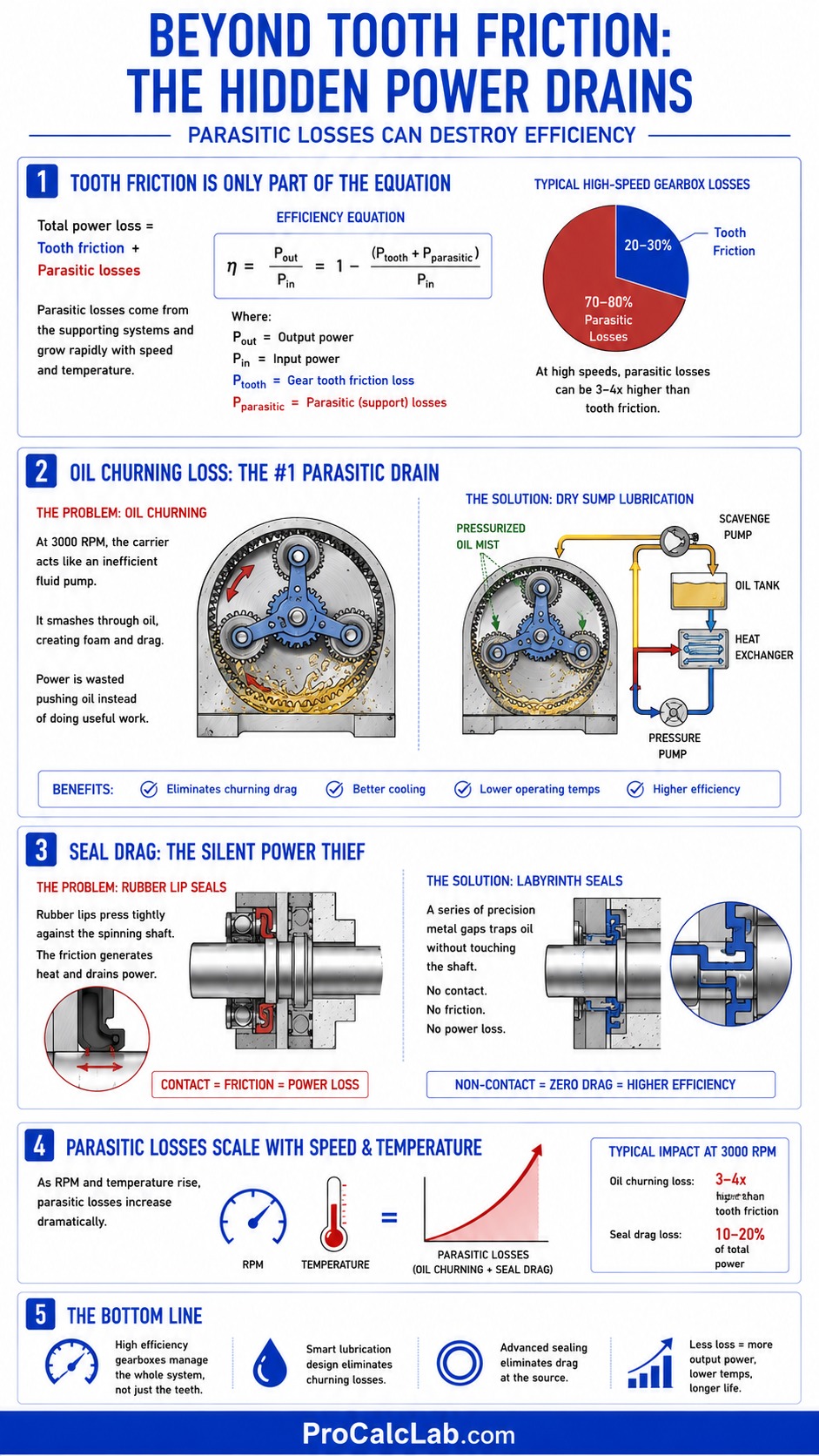
The most severe parasitic drain is oil churning loss. At 3000 revolutions per minute, a planetary carrier acts like an incredibly inefficient fluid pump. It has to smash its way through thick gear oil, whipping it into a heavy foam. The kinetic energy required to push that oil out of the way is stolen directly from your motor output. In high-speed applications, churning losses can consume 3 to 4 times more power than actual gear tooth friction.
💧 To combat this, engineers utilize dry sump lubrication. Instead of letting the gears sit in a deep bath of oil, scavenge pumps suck the oil out of the housing, run it through a heat exchanger, and spray a highly pressurized mist directly onto the gear teeth precisely where they mesh. This eliminates churning drag entirely while providing superior cooling.
Another major source of efficiency loss is seal drag. The output shaft of the gearbox must pass through the steel housing. To keep the oil inside and the dirt outside, tight rubber lip seals are clamped around the spinning shaft. The physical friction of this rubber squeezing the steel shaft generates heat and drains power. High-efficiency designs replace rubber lip seals with non-contact labyrinth seals. These seals use a complex maze of microscopic metal gaps to trap oil without ever physically touching the spinning shaft, eliminating friction entirely.
Engineering Data and System Tolerances
To assist in your initial design phases, the following tables provide baseline metrics used by professional engineering departments to estimate efficiency drops based on stage complexity and manage thermal loads.
Table 1: Planetary Gearbox Stage Efficiency Estimates
| Number of Stages | Typical Ratio Range | Estimated Mechanical Efficiency |
|---|---|---|
| 1 Stage | 3:1 up to 10:1 | 96% to 98% |
| 2 Stage | 10:1 up to 100:1 | 92% to 95% |
| 3 Stage | 100:1 up to 1000:1 | 88% to 91% |
| 4 Stage | 1000:1 up to 10000:1 | 84% to 87% |
Table 2: Gearbox Thermal Management Guidelines Metric
| Operating State | Oil Temperature Celsius | Lubrication Behavior and Action Required |
|---|---|---|
| Cold Start | 10 to 30 | High viscosity. Churning losses peak. Limit high RPM operation. |
| Optimal Operation | 50 to 75 | Ideal viscosity film thickness. Maximum power transfer efficiency. |
| Warning Zone | 85 to 95 | Film thickness degrading. Activate external cooling circuits. |
| Critical Failure | Over 100 | Thermal breakdown of additives. Rapid gear scoring imminent. Shutdown required. |
Table 3: Gearbox Thermal Management Guidelines Imperial
| Operating State | Oil Temperature Fahrenheit | Lubrication Behavior and Action Required |
|---|---|---|
| Cold Start | 50 to 85 | High viscosity. Churning losses peak. Limit high RPM operation. |
| Optimal Operation | 120 to 165 | Ideal viscosity film thickness. Maximum power transfer efficiency. |
| Warning Zone | 185 to 205 | Film thickness degrading. Activate external cooling circuits. |
| Critical Failure | Over 212 | Thermal breakdown of additives. Rapid gear scoring imminent. Shutdown required. |
Floating Sun Gears and Perfect Load Sharing
One final, critical detail regarding planetary efficiency involves manufacturing reality. The mathematics we used assume that every single planet gear takes an exactly equal share of the torque. If we have 4 planets, we assume each takes 25% of the load. In reality, perfectly equal load sharing is impossible.
⚙ Microscopic variations in machining tolerance mean that 1 planet gear will always engage slightly earlier than the others. If the system is built rigidly, that single planet gear might take 60% of the entire system load, causing rapid, catastrophic bearing failure and intense friction spikes.
To solve this, advanced gearboxes employ a floating sun gear. Instead of supporting the sun gear on heavy internal bearings, the sun gear is left completely unsupported inside the center of the planet gears. It is connected to the input shaft via a flexible spline. When torque is applied, the sun gear is free to physically shift off its absolute center by a few thousandths of an inch. This microscopic shift allows the sun gear to press equally against all the planet gears, forcing perfect load distribution regardless of minor manufacturing defects. This engineering trick dramatically reduces wear, lowers operating temperatures, and preserves the theoretical efficiency of the system.
Final Engineering Considerations
Mastering epicyclic gear efficiency goes far beyond simply multiplying a baseline friction coefficient. It demands an understanding of how kinematic coupling power bypasses physical mesh friction, how viscous oil drag consumes kinetic energy at high speeds, and how floating components compensate for the physical realities of steel machining.

Whether you are designing a precision robotic wrist joint or a massive industrial crushing mill, you must calculate these factors rigorously. Overestimating efficiency leads to burned-out motors and melted bearings. Treat your gearbox as a dynamic thermodynamic system, manage your parasitic losses through clever lubrication, and your drivetrain will outlast the machinery it was built to drive.
Literature
- Radzimovsky, Eugene I. Kinematics and Dynamics of Machinery. Allyn and Bacon. A foundational engineering text detailing the precise mathematical derivations of epicyclic gear ratios and coupling power efficiencies.
- Maitra, Gitin. Handbook of Gear Design. McGraw-Hill Professional. An exhaustive reference manual covering involute tooth profiling, contact stresses, and lubrication film thickness calculations for heavy industry.
- Dudley, Darle W. Dudley’s Handbook of Practical Gear Design and Manufacture. CRC Press. The definitive industry standard for understanding parasitic losses, churning drag, and manufacturing tolerances in complex transmissions.

David Parry — Senior Engineering Analyst
Specializing in electronics and physics-based simulations with 20+ years of engineering experience. David ensures the mathematical and physical accuracy of the tools at ProCalcLab.