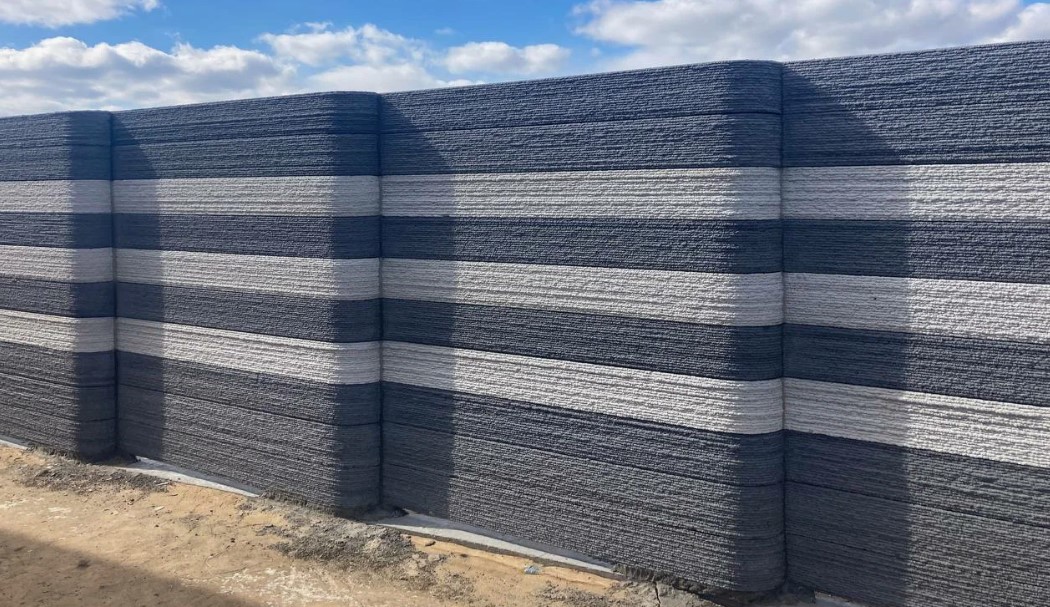
A few years ago, a developer in Colorado constructed a 500-foot masonry privacy fence along the rear boundary of a new commercial subdivision. The crew pulled their measurements off an old wooden utility pole they assumed was the property corner. They were wrong by 14 inches. The entire structure encroached on a municipal utility easement. The city forced them to demolish the $45000 wall and rebuild it.

In the field, we often see contractors treat property boundaries as simple, straight lines that can be laid out with a tape measure and a good guess. Real-world boundary design is strict geometric mapping, and guessing will eventually cost you a massive amount of money.
Property lines are rarely perfect squares or rectangles. Because land is divided around geographic features, roads, and historical claims, almost every residential and commercial lot is an irregular polygon. Designing a fence layout requires translating the legal descriptions found on a survey map into physical, real-world coordinates. This article breaks down the coordinate geometry used by professional surveyors, explains how to calculate exact linear footage for material orders, and covers the physical engineering required to keep your fence standing under severe wind loads.
Table of Contents
The Core Theory of Boundary Geometry
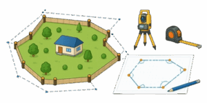
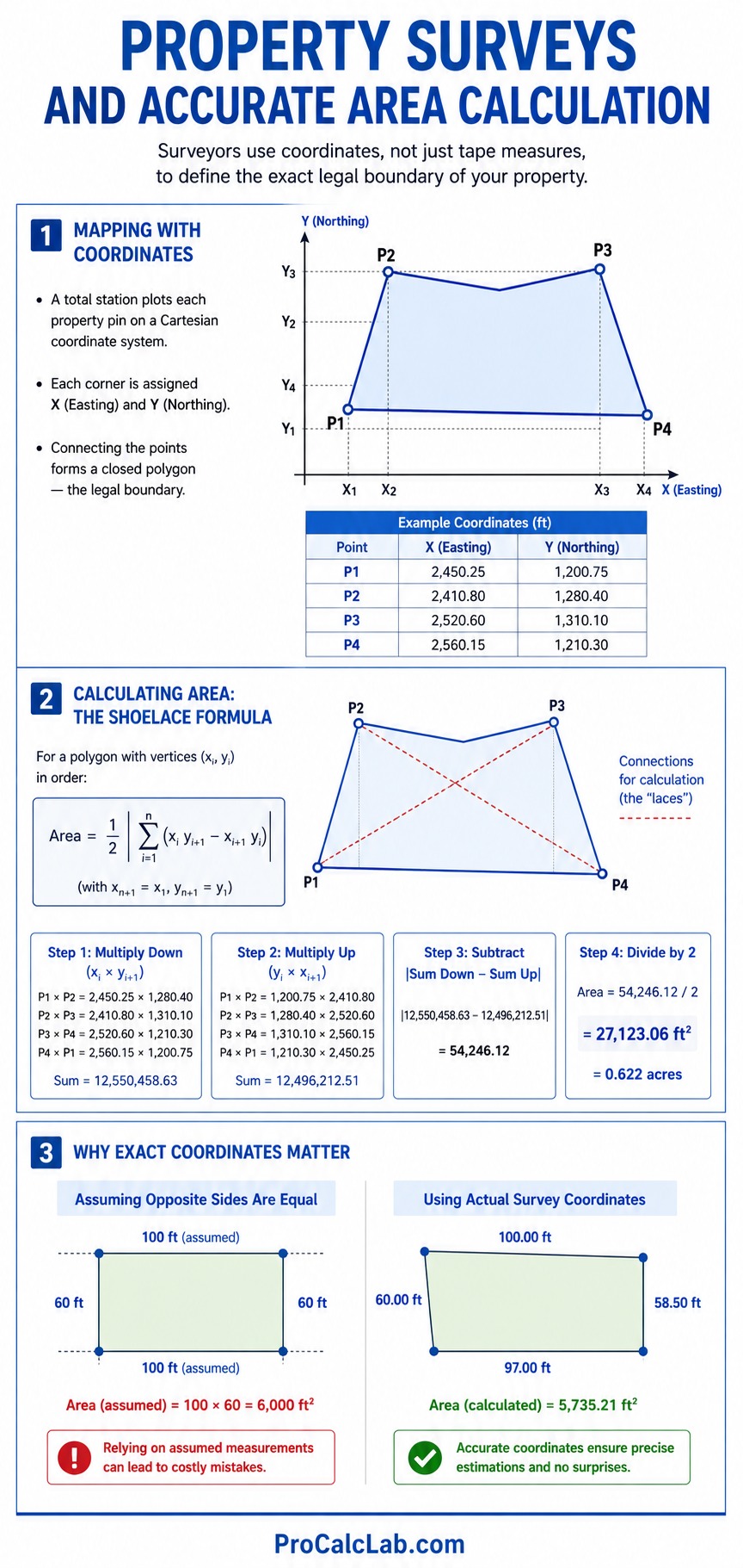
When a licensed surveyor maps a property, they do not just measure the distance from one corner to the next. They use a total station to plot each property pin on a Cartesian coordinate system. Every corner of the lot is assigned a specific X and Y coordinate, usually referred to as Easting and Northing. By connecting these coordinate points, they create a closed polygon that represents the exact legal boundary of the land.
📊 This coordinate system is the absolute truth of the property. Physical landmarks like trees, old fence lines, and even roads can shift or be moved over time. The geometric coordinates do not change. To find the exact perimeter of the lot, we calculate the straight-line distance between each set of coordinates. To find the exact square footage or acreage of the enclosed lot, we apply a mathematical algorithm known as the Shoelace Formula.
A common mistake during material estimation is assuming opposite sides of a lot are equal just because they look parallel on a drawing. If the front property line is 100 feet long, the rear line might be 97 feet long. If you order materials based on the front measurement, you will end up with surplus materials or, worse, a shortage that delays your project.
The Mathematics of Perimeter and Area
📐 To accurately design our fence layout, we need 2 specific formulas. The first is the Distance Formula, which is derived from the Pythagorean theorem. It calculates the exact linear distance between 2 coordinate points. We use this to determine how much fencing material we need.
The Distance Formula is written as follows:
D = √[(X2 – X1)2 + (Y2 – Y1)2]
The variables are defined as follows:
- D represents the linear distance between the points.
- X1, Y1 represent the coordinates of the starting corner.
- X2, Y2 represent the coordinates of the ending corner.
The second equation is the Shoelace Formula, also known as the Surveyor’s formula. It calculates the area of any closed polygon, no matter how irregular the shape is, based entirely on its vertex coordinates.
The Shoelace Formula is written as follows:
Area = 0.5 × |(X1×Y2 + X2×Y3 + X3×Y4 + X4×Y1) – (Y1×X2 + Y2×X3 + Y3×X4 + Y4×X1)|
Step-by-Step Coordinate Calculation
Let us apply this to a real-world scenario. You are laying out a fence for an irregular 4-sided property. You pull the surveyor data and establish the 4 property corners on a grid measured in feet.
- Point 1 Front Left: X = 0, Y = 0
- Point 2 Front Right: X = 80, Y = 0
- Point 3 Rear Right: X = 100, Y = 60
- Point 4 Rear Left: X = 20, Y = 90
First, we calculate the total linear footage required for the fence by applying the Distance formula to each property line.
Line 1 to 2 Front boundary:
D = √[(80 – 0)2 + (0 – 0)2] = √[6400 + 0] = 80.0 ft
Line 2 to 3 Right boundary:
D = √[(100 – 80)2 + (60 – 0)2] = √[202 + 602] = √[400 + 3600] = 63.2 ft
Line 3 to 4 Rear boundary:
D = √[(20 – 100)2 + (90 – 60)2] = √[(-80)2 + 302] = √[6400 + 900] = 85.4 ft
Line 4 to 1 Left boundary:
D = √[(0 – 20)2 + (0 – 90)2] = √[(-20)2 + (-90)2] = √[400 + 8100] = 92.2 ft
Total Fence Length = 80.0 + 63.2 + 85.4 + 92.2 = 320.8 feet of fencing material.
Next, we use the Shoelace formula to find the exact area of the lot. We multiply diagonally down to the right, then diagonally down to the left, and subtract the difference.
Rightward sum = (0 × 0) + (80 × 60) + (100 × 90) + (20 × 0) = 0 + 4800 + 9000 + 0 = 13800
Leftward sum = (0 × 80) + (0 × 100) + (60 × 20) + (90 × 0) = 0 + 0 + 1200 + 0 = 1200
Area = 0.5 × |13800 – 1200| = 0.5 × 12600 = 6300 square feet.
Calculating the dimensions of an irregular 12-sided lot by hand leaves a massive margin for arithmetic error. From a practical standpoint, this is why modern engineers recommend running your survey coordinates through our polygon perimeter and area calculator. It instantly processes the Cartesian geometry, giving you the exact linear footage for material ordering and the precise acreage for your site plans.
Engineering the Physical Layout
Once you have the mathematical perimeter, you must translate that line into physical posts in the ground. A solid privacy fence acts as a massive sail. When wind hits a 6-foot high solid panel, it creates an overturning moment at the base of the post. If the post spacing is too wide or the footings are too shallow, a 50 mph wind gust will snap the posts at the ground line or uproot the concrete footings entirely.

The standard engineering practice is to adjust your post spacing and footing depth based on the height of the fence and the expected wind load. The table below outlines standard safety minimums for solid privacy fences.
Table 1: Post Spacing and Footing Depth Requirements
| Fence Height, ft / m | Max Post Spacing, ft / m | Min Footing Depth, in / mm |
|---|---|---|
| 4.0 / 1.2 | 8.0 / 2.4 | 24 / 600 |
| 6.0 / 1.8 | 8.0 / 2.4 | 36 / 900 |
| 8.0 / 2.4 | 6.0 / 1.8 | 48 / 1200 |
| 10.0 / 3.0 | 4.0 / 1.2 | 60 / 1500 |
Field Applications and Troubleshooting
Taking a geometric plan and building it in the dirt introduces environmental variables that math alone cannot solve. You must anticipate elevation changes, locate actual boundary markers, and account for subsurface conditions.
Horizontal Distance vs. Slope Distance
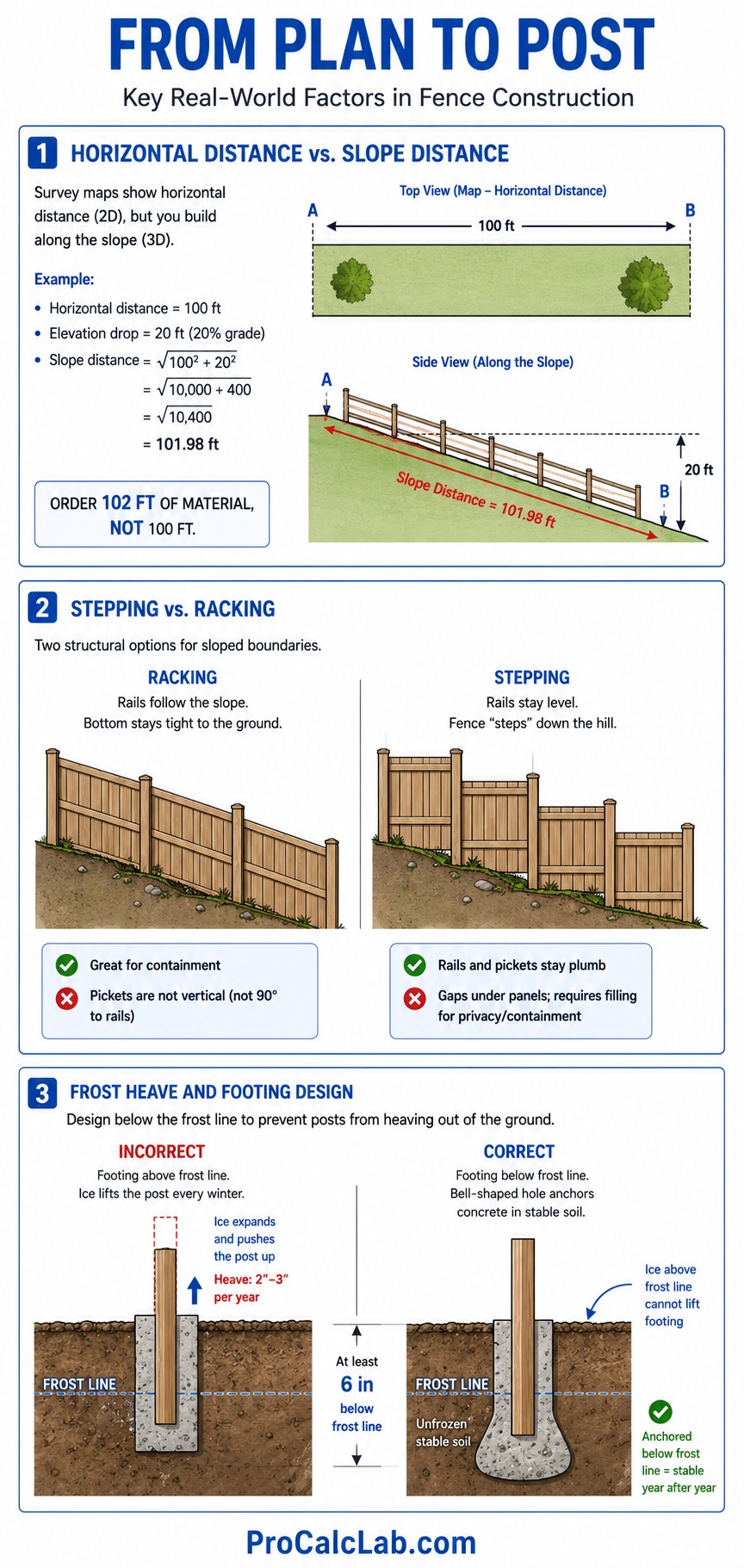
One of the most frequent errors made by DIYers and junior contractors involves topography. Survey maps display horizontal distance. This is a 2D representation, looking straight down from the sky. However, if your property line runs down a steep hill, you must build the fence along the slope distance, which is physically longer than the horizontal distance.
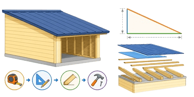
If a survey map shows a 100-foot rear boundary, but that boundary drops down a hill with a 20% grade, laying exactly 100 feet of fencing will leave a massive gap at the corner. To find the actual physical material length required, you must use the Pythagorean theorem again, treating the horizontal distance and the elevation drop as the legs of a right triangle.
If the horizontal distance is 100 feet and the elevation drops 20 feet, the actual slope distance is √[1002 + 202] = √[10000 + 400] = 101.98 feet. You must order 102 feet of material, not 100 feet.
Stepping versus Racking
When dealing with sloped boundaries, you have 2 structural options for installing the panels. Racking means building the fence so the horizontal rails run parallel to the sloping ground. This keeps the bottom of the fence tight to the dirt, which is excellent for containing pets, but it forces the vertical pickets out of a perfect 90-degree alignment with the rails.
Stepping involves keeping the horizontal rails perfectly level, resulting in a stair-step appearance as the fence moves down the hill. This requires taller posts and leaves triangular gaps under the fence panels, which must be filled with landscaping or custom-cut boards if privacy and containment are strictly required.
Frost Heave and Footing Design
If you build a fence in a northern climate, you must design for frost heave. When water freezes in the soil, it expands, pushing upward with immense hydraulic force. If you pour a concrete fence footing that ends above the regional frost line, the winter ice will grip the concrete and push the entire fence post out of the ground by 2 to 3 inches every year.
To prevent this, you must dig the post holes at least 6 inches below the local frost line. Furthermore, the hole should be bell-shaped, meaning the bottom of the hole is slightly wider than the top. This anchors the concrete deep in the unfrozen soil, making it physically impossible for the expanding frost layer above to lift the footing.
Summary and Professional Literature
Designing a boundary fence is an exercise in applied geometry and structural engineering. The lines on a survey map are not suggestions; they are legally binding coordinates that dictate exactly where you can and cannot build. By translating those coordinates into exact linear dimensions using the Distance Formula and verifying your lot size with the Shoelace Formula, you eliminate guesswork from your material estimation.
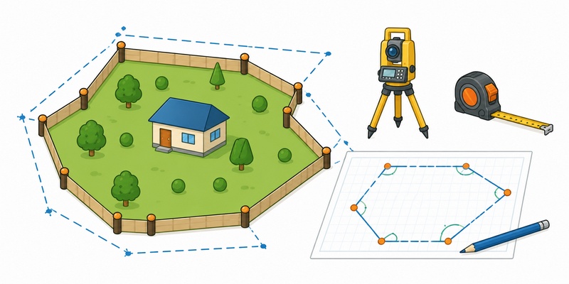
Always respect the physical forces at play. Wind loads and frost heave will dismantle a poorly engineered fence in a single season. Dig deep footings, account for slope distances, and trust the mathematics over your naked eye. Utilizing digital calculation tools allows you to quickly verify your geometry in the field, ensuring every post is placed perfectly on the legal boundary.
Recommended Technical References
- Kavanagh, Barry F. Surveying: Principles and Applications. Pearson. A comprehensive textbook covering coordinate geometry, topographic mapping, and the mathematics of legal boundary determination.
- American Society of Civil Engineers. Minimum Design Loads and Associated Criteria for Buildings and Other Structures ASCE 7. The definitive engineering standard for calculating wind loads on free-standing walls and solid fences.
- Ching, Francis D. K. Building Construction Illustrated. John Wiley and Sons. A highly detailed visual guide illustrating proper footing design, frost line depth requirements, and structural post anchoring techniques.

Markus Fletcher — Structural Design Specialist
Expert in structural integrity, 3D modeling, and applied mathematics. Markus focuses on creating precise tools for construction professionals and DIY engineers.