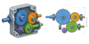
During a high-stakes packaging machinery overhaul at a manufacturing plant in Ohio, a team of field mechanics spent 12 hours trying to force a replacement 50-horsepower motor into a tight conveyor housing. The design engineers had squeezed a 2-stage gear reducer into a compact space, leaving exactly 0.02 inches of clearance between the gearbox casing and the structural steel frame. When the motor reached its operating temperature of 165 degrees Fahrenheit, the aluminum gearbox housing expanded. This expansion pushed the casing against the frame, warping the intermediate shaft alignment by a mere 0.006 inches. Within 3 days of continuous operation, the high-pitched scream of screaming metal filled the floor as the gears stripped their teeth, halting a production line that cost the company $8000 per hour.
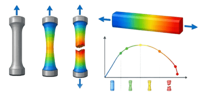
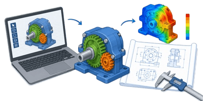

In the field, we often see junior engineers treat gear design as a simple software exercise. They select standard gear catalogs, click a few buttons in a CAD program, and assume the parts will mesh perfectly. But when you are forced to design for tight spaces, such as robotic arms, aerospace actuators, or compact automotive transaxles, you quickly learn that gear design is a brutal game of fractions. You must manage physical space constraints while maintaining absolute center-line alignment under heavy dynamic loads.
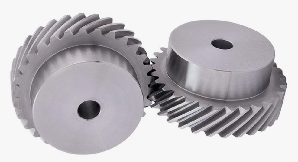
This article details the underlying physics of gear geometry, explains the exact mathematics of center distance calculations, and provides the formulas required to lay out a coaxial, space-saving gear train. This article supports our gear and gear train calculator, which enables rapid design iterations by letting you instantly calculate gear ratios, pitch diameters, and center distances without manual arithmetic errors.
Table of Contents
The Physics of Involute Gear Geometry
To design a compact gear train, you must first master the geometry of the individual teeth. Modern industrial machinery almost exclusively uses the involute tooth profile. An involute is a curve traced by a point on a taut string as it unwinds from a cylinder. The beauty of the involute profile is that it allows for minor variations in center-to-center distance without changing the instantaneous velocity ratio between the two shafts. This is a critical safety margin in real-world manufacturing where perfect alignment is impossible to maintain.
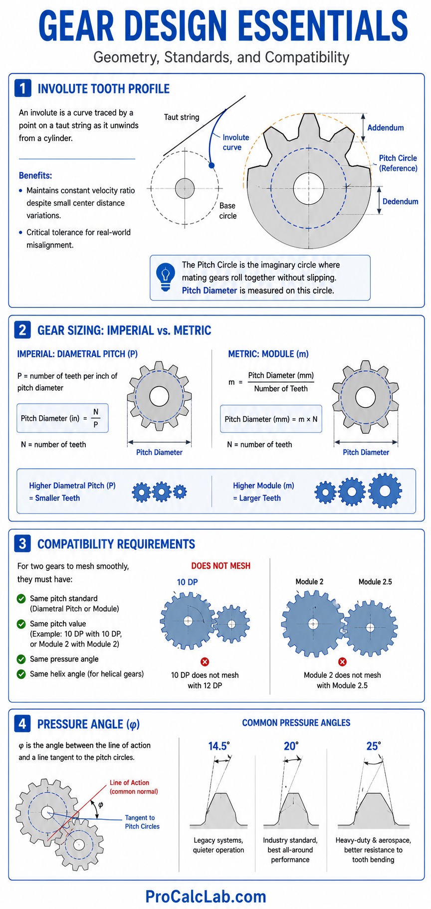
The primary geometric parameter that dictates gear size is the pitch circle. This is an imaginary circle where the mating gears slip-free against each other. When we talk about the diameter of a gear, we are referring to the Pitch Diameter, not the outside diameter of the metal teeth. The teeth extend above the pitch circle by a distance called the addendum, and they dip below it by a distance called the dedendum.
⚙ In the Imperial system, gear sizes are governed by Diametral Pitch, which represents the number of teeth per inch of pitch diameter. In the Metric system, we use the Module, which is the ratio of the pitch diameter in millimeters to the number of teeth. These two systems are inversely related. A higher Diametral Pitch means smaller teeth, while a higher Module means larger teeth.
To ensure two gears mesh smoothly, they must share the exact same pitch standard. You cannot mesh a 10 Diametral Pitch gear with a 12 Diametral Pitch gear, nor can you mesh a Module 2 gear with a Module 2.5 gear. They must also share the same pressure angle, which is the angle between the line of action and a line tangent to the pitch circles. The industry standard pressure angle is 20 degrees, which offers an excellent balance between load capacity and quiet operation. Legacy systems sometimes use a 14.5-degree pressure angle, while heavy-duty aerospace designs utilize a 25-degree pressure angle to resist tooth bending fatigue.
The Mathematics of Center-Line Alignment
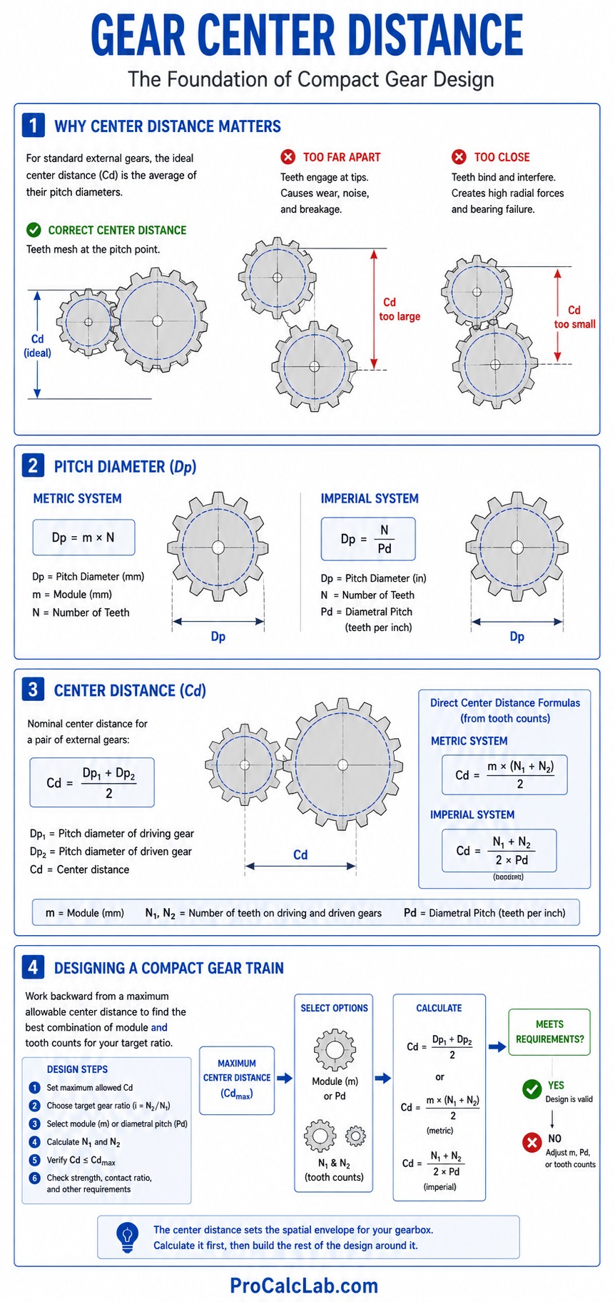
✍ The core challenge of compact gear design is placing shafts close together while ensuring the teeth mesh at the precise pitch point. If the shafts are placed too far apart, the teeth will engage only at their tips, causing rapid wear, high noise levels, and potential tooth breakage. If the shafts are placed too close together, the teeth will bind, generating massive radial forces that will quickly destroy the shaft bearings. For a standard pair of external gears, the ideal center distance is the average of their pitch diameters.
In a Metric system, the Pitch Diameter of a gear is calculated as follows:
Dp = m × N
The variables are defined as follows:
- Dp represents the Pitch Diameter of the gear in millimeters.
- m represents the gear Module in millimeters.
- N represents the total number of teeth on the gear.
In an Imperial system, the Pitch Diameter is calculated using the Diametral Pitch:
Dp = N / Pd
Where Pd represents the Diametral Pitch of the gear in teeth per inch.
Once we have the pitch diameters for both mating gears, we calculate the exact nominal Center Distance:
Cd = [Dp1 + Dp2] / 2
Where Cd represents the Center Distance, and Dp1 and Dp2 represent the pitch diameters of the driving and driven gears, respectively. By substituting our pitch diameter equations, we can calculate the center distance directly from the tooth counts.
For Metric systems, the direct Center Distance formula is:
Cd = m × [N1 + N2] / 2
For Imperial systems, the direct Center Distance formula is:
Cd = [N1 + N2] / [2 × Pd]
These formulas establish the nominal spatial envelope. When designing a compact gearbox, you must work backward from a fixed maximum center distance to find the optimum combination of module and tooth counts that delivers your target gear ratio.
The Coaxial Gear Train Challenge
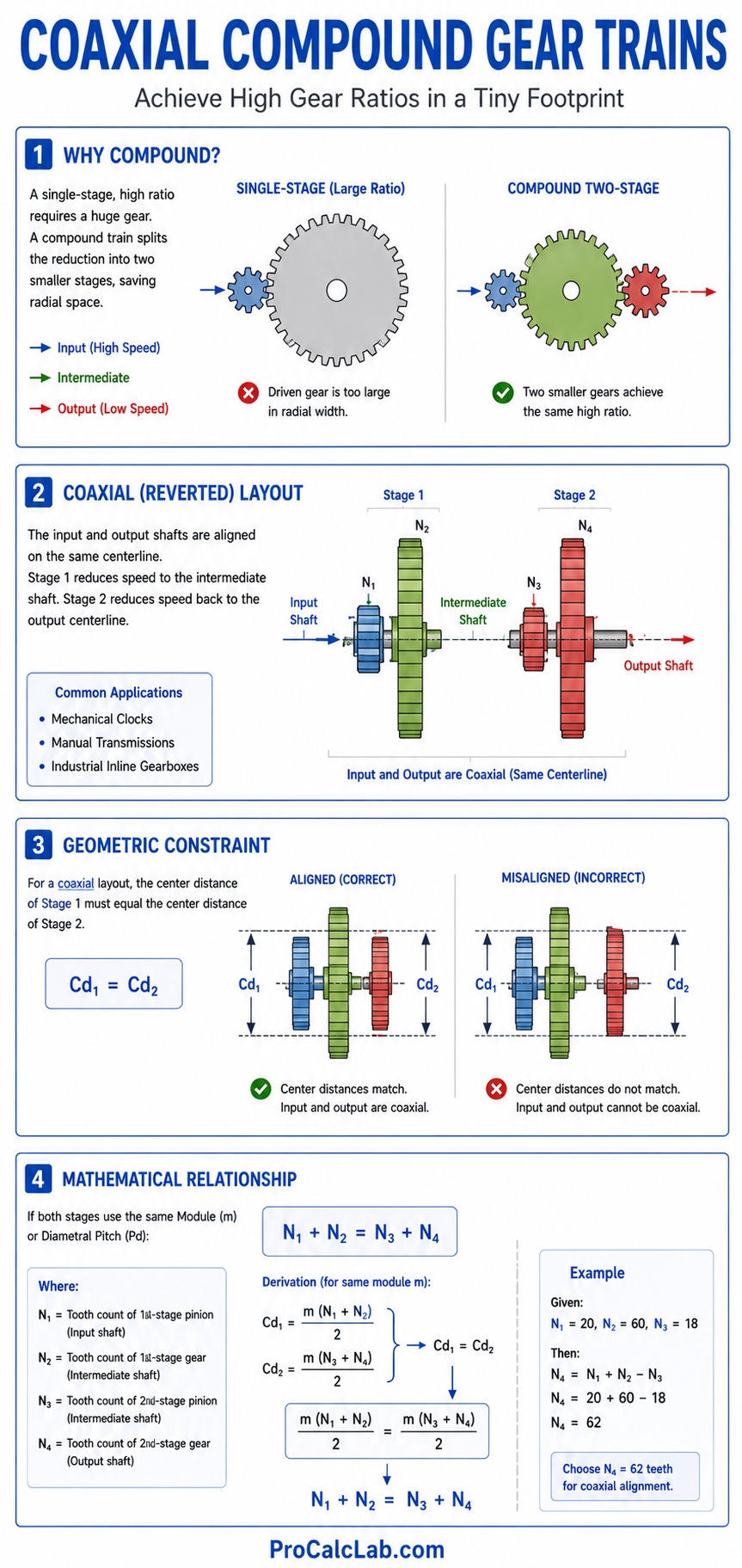
When space is extremely restricted in the radial direction, a single-stage gear reduction with a large gear ratio is useless because the driven gear will be too wide to fit. To solve this, we use a compound gear train. By splitting the total reduction into 2 separate stages, we can achieve massive gear ratios in a tiny footprint.
📊 To make the system even more compact, we can design a coaxial compound gear train, also known as a reverted gear train. In this layout, the input shaft and the output shaft are aligned on the exact same centerline. The 1st stage reduces speed to an intermediate shaft, and the 2nd stage reduces speed from the intermediate shaft back to the output centerline. This is the layout used in mechanical clocks, manual automotive transmissions, and industrial inline gearboxes.
A coaxial layout introduces a strict geometric constraint. The center distance of the 1st stage must align exactly with the center distance of the 2nd stage. If they do not align, the input and output shafts cannot share the same centerline. The coaxial mathematical constraint is written as follows:
Cd1 = Cd2
If we use the same Module or Diametral Pitch for both stages of the gear train, this constraint simplifies to a direct relationship between the tooth counts of the 4 gears:
N1 + N2 = N3 + N4
The variables are defined as follows:
- N1 represents the tooth count of the 1st-stage pinion on the input shaft.
- N2 represents the tooth count of the 1st-stage gear on the intermediate shaft.
- N3 represents the tooth count of the 2nd-stage pinion on the intermediate shaft.
- N4 represents the tooth count of the 2nd-stage gear on the output shaft.
Step-by-Step Coaxial Layout Calculation
Let us walk through a real-world design scenario. We need to design a compact inline gear reducer for a robotic joint. The total target gear ratio is 12:1. The input and output shafts must be coaxial to fit inside the cylindrical arm housing. To maintain high tooth strength under heavy load, we will use a Module of 2 millimeters for all gears.
Our design parameters are:
- Target Total Ratio, Rtotal = 12:1
- Common Module, m = 2 mm
- Pressure Angle = 20 degrees
- Minimum Pinion Tooth Count = 16 teeth to prevent undercutting and strength loss
Step 1: Distribute the Gear Ratio
To keep the gear sizes balanced and compact, we want to distribute the 12:1 ratio across 2 stages. Let us target a 4:1 reduction for the 1st stage, and a 3:1 reduction for the 2nd stage.
Stage 1 Ratio, R1 = 4:1
Stage 2 Ratio, R2 = 3:1
Verification: Rtotal = R1 × R2 = 4 × 3 = 12. The distribution is mathematically correct.
Step 2: Define Tooth Relationships
Based on our stage ratios, we can express the gear teeth counts as multiples of their mating pinions:
N2 = 4 × N1
N4 = 3 × N3
Step 3: Apply the Coaxial Constraint
Because we are using a common Module of 2 mm, our coaxial tooth sum equation must balance:
N1 + N2 = N3 + N4
We substitute our ratio relationships into this equation:
N1 + 4 × N1 = N3 + 3 × N3
5 × N1 = 4 × N3
This means the ratio of our pinion teeth must satisfy this exact relationship:
N3 = 1.25 × N1
Step 4: Solve for Integer Tooth Counts
Because you cannot manufacture a fraction of a gear tooth, both N1 and N3 must be whole integers. Since N3 is 1.25 times N1, N1 must be a multiple of 4 to ensure N3 is an integer.
Let us test the smallest valid multiple of 4 that satisfies our minimum tooth constraint of 16:
Let N1 = 16 teeth.
Then we calculate N2:
N2 = 4 × 16 = 64 teeth.
Next, we calculate N3:
N3 = 1.25 × 16 = 20 teeth. This is greater than our minimum constraint of 16, so it is a safe design.
Finally, we calculate N4:
N4 = 3 × 20 = 60 teeth.
Let us verify the coaxial tooth sum: 16 + 64 = 80, and 20 + 60 = 80. The sums match perfectly. The coaxial constraint is satisfied.
Step 5: Calculate Physical Dimensions
Now, we convert these tooth counts into physical sizes using our Module of 2 mm.
Pitch Diameter of Pinion 1:
Dp1 = 2 × 16 = 32 mm
Pitch Diameter of Gear 2:
Dp2 = 2 × 64 = 128 mm
Pitch Diameter of Pinion 3:
Dp3 = 2 × 20 = 40 mm
Pitch Diameter of Gear 4:
Dp4 = 2 × 60 = 120 mm
Step 6: Calculate Center Distance and Housing Clearance
The nominal Center Distance for both stages is:
Cd = m × [N1 + N2] / 2
Cd = 2 × 80 / 2 = 80 mm
This means the intermediate shaft must be positioned exactly 80.000 mm away from the input/output centerline.
To find the minimum clearance envelope inside the cylindrical arm housing, we must look at the largest gear in the train, which is Gear 2 with a pitch diameter of 128 mm. The actual outside diameter of a standard spur gear is the pitch diameter plus 2 addendums. For a standard module gear, the addendum is equal to the module.
Outside Diameter of Gear 2:
Do2 = Dp2 + 2 × m
Do2 = 128 + 2 × 2 = 132 mm
Because Gear 2 is spinning on the intermediate shaft which is offset by 80 mm, the maximum radial sweep of our gear train from the main centerline is calculated as:
Rmax = Cd + [Do2 / 2]
Rmax = 80 + [132 / 2] = 80 + 66 = 146 mm
This means our gear train requires a cylindrical housing with an internal diameter of at least 292 mm to spin freely without striking the walls. If your physical housing constraint is 250 mm, you must redesign the system using a smaller module, such as Module 1.5, to shrink the physical footprint while maintaining the same mathematical ratios.
Dimensional Reference Charts for Gear Layouts
To speed up your initial design phases and keep your shaft spacings accurate, we have compiled geometric metrics for common module and diametral pitch standards. These numbers represent the foundation of compact gearbox layouts.
Table 1: Standard Metric Module Geometry
| Module, mm | Addendum, mm | Dedendum, mm |
|---|---|---|
| 1 | 1.0 | 1.250 |
| 1.5 | 1.5 | 1.875 |
| 2 | 2.0 | 2.500 |
| 2.5 | 2.5 | 3.125 |
| 3 | 3.0 | 3.750 |
| 4 | 4.0 | 5.000 |
Table 2: Standard Imperial Diametral Pitch Geometry
| Diametral Pitch, 1/in | Addendum, in | Dedendum, in |
|---|---|---|
| 24 | 0.0417 | 0.0521 |
| 20 | 0.0500 | 0.0625 |
| 16 | 0.0625 | 0.0781 |
| 12 | 0.0833 | 0.1042 |
| 10 | 0.1000 | 0.1250 |
| 8 | 0.1250 | 0.1563 |
Practical Field Application and Troubleshooting
Translating theoretical centerlines into functioning metal machinery reveals physical challenges that CAD models hide. In the field, you must manage tolerances, deflection, and thermal expansion to keep your compact gear train from self-destructing.
Understanding and Measuring Backlash
In a perfect mathematical model, gear teeth mesh with zero clearance. In the physical world, zero clearance means immediate binding as soon as the gears begin to rotate. To prevent this, we intentionally design a small gap between the non-driving faces of the mating teeth. This gap is known in the shop as backlash.
Without sufficient backlash, lubricating oil cannot enter the mesh zone, causing metal-on-metal friction that results in rapid wear and overheating. However, if you have too much backlash, the gears will suffer from excessive play. This play creates positioning errors in robotic joints and causes severe impact loads when the motor reverses direction.
In the field, we measure backlash by locking the driving gear shaft in place, mounting a dial indicator against a tooth of the driven gear, and gently rocking the driven gear back and forth. For a Module 2 gear train, standard backlash should measure between 0.08 mm and 0.15 mm. If your backlash is too low, you must slightly increase the physical center distance of your shafts, or thin the teeth during manufacturing.
Deflection and Bearing Preload
When gears transmit torque, the teeth push against each other along the line of action. This force has 2 primary components: a tangential force that rotates the gear, and a radial force that tries to push the 2 shafts apart. Under heavy load, these forces will cause the shafts to bend and the gearbox housing to deflect.
If your shafts bend by even 0.05 mm, the gear teeth will tilt relative to each other. This misaligns the face contact, concentrating the entire torque load onto the corners of the teeth instead of distributing it evenly across the full face width. This concentrated load causes localized metal fatigue, leading to pitting, cracking, and eventual tooth shear.
To prevent shaft deflection in compact gearboxes, we utilize high-precision tapered roller bearings or angular contact ball bearings. These bearings must be installed with a precise axial preload. This preload eliminates all internal clearance within the bearing assembly, ensuring the shafts remain rigidly locked on their physical centerlines even under peak torque loads.
Undercutting and Minimum Tooth Limits
When you are designing for compact spaces, the natural temptation is to reduce the size of your pinion gears by choosing very low tooth counts, such as 10 or 12 teeth. In standard 20-degree pressure angle systems, this creates a severe manufacturing defect known as undercutting.
During the gear cutting process, the tool must cut deep into the flank of a low-tooth gear to clear the tips of the mating gear teeth. This deep cut removes a significant portion of the metal at the root of the pinion tooth, making the base of the tooth extremely narrow. This structural thinning drastically reduces the bending strength of the gear, leading to sudden tooth shear under shock loads. To ensure structural safety, standard engineering design rules dictate a minimum tooth limit of 17 teeth for standard 20-degree pressure angle spur gears. If you must go smaller, you must specify custom profile-shifted gears where the tooth geometry is modified to retain root strength.
Summary and Professional Design Tips
⚙ Designing compact gear trains is a delicate balancing act between mathematical constraints and physical realities. A coaxial layout provides a highly efficient, space-saving inline design, but it demands absolute precision in your tooth count selections to satisfy the center distance matching rules. By understanding the geometry of the involute profile, calculating exact nominal centerlines, and leaving sufficient room for backlash and thermal expansion, you ensure your drive systems run quietly and reliably for years.
Always double-check your housing clearances based on outside diameters rather than pitch diameters, verify your bearing preloads to prevent shaft deflection under radial load, and keep your pinion tooth counts high enough to prevent dangerous undercutting. For rapid, error-free engineering design, running your layouts through our gear and gear train calculator can instantly confirm your physical centerlines and prevent costly alignment errors before you send your designs to the machine shop.
Literature
- American Gear Manufacturers Association. AGMA 2001-D04: Fundamental Rating Factors and Calculation Methods for Involute Spur and Helical Gear Teeth. The primary standard for calculating gear strength, wear resistance, and safety margins.
- Shigley, Joseph E., and Mischke, Charles R., published in 2011. Mechanical Engineering Design. McGraw-Hill. The definitive academic textbook covering shaft layout, bearing selection, and gear train geometry.
- International Organization for Standardization. ISO 6336-1: Calculation of Load Capacity of Spur and Helical Gears. A critical international standard detailing tooth profile modifications, backlash limits, and contact ratio calculations.

David Parry — Senior Engineering Analyst
Specializing in electronics and physics-based simulations with 20+ years of engineering experience. David ensures the mathematical and physical accuracy of the tools at ProCalcLab.