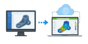
For decades, mechanical and civil engineering relied exclusively on monolithic desktop software. If you wanted to design a steel truss or model a planetary gear assembly, you needed a workstation that cost upwards of 5000 dollars. These machines housed massive multi-core processors and specialized graphics cards just to calculate the boundary representations of solid objects. When you finished a design, sharing it with a client or a manufacturing floor meant exporting a STEP or IGES file. 99% of the time, the recipient could not open the file without purchasing their own expensive software license.
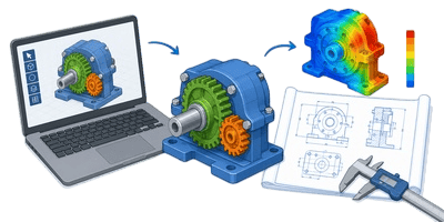

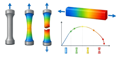
In the field, we often see this exact bottleneck cripple project timelines. A client requests a small dimension change to a custom piece of furniture or a structural bracket. The engineer has to open the heavy CAD file, modify the parametric sketch, rebuild the entire assembly, regenerate the drawing sheets, export a 3D PDF, and email it back. This single iteration can consume 2 to 3 hours of billable time. The industry desperately needed a way to decouple the geometry engine from the local desktop hardware and move it into the cloud.
Table of Contents
The Shift to Web-Based Parametric Engineering
📱 The solution arrived with the maturation of WebGL and WebAssembly technologies. Instead of relying on a local CAD kernel like Parasolid to calculate exact mathematical curves, web simulations utilize the client computer graphics processing unit to render lightweight polygonal meshes. A traditional CAD model stores a cylinder as a mathematical equation defining a circle extruded along a vector. A web viewer translates that exact cylinder into a mesh of 100s of small flat triangles.
This conversion reduces file sizes by over 90%, allowing complex 3D models to stream across a standard internet connection in milliseconds. But the true evolution is not just viewing static models. Modern web tools embed parametric engineering rules directly into the JavaScript running in the browser. You no longer need a 10 gigabyte software installation to configure an assembly. The browser itself handles the structural logic, the spatial transformations, and the instant visual feedback.
The Mechanics of Browser-Based 3D Transformations
To understand how these web tools function without a dedicated CAD engine, we must examine the underlying mathematics of 3D space. When a user drags a slider on a web page to lengthen a steel beam, the browser does not redraw the object from scratch. Instead, it applies an affine transformation matrix to the existing vertices of the 3D mesh. Affine transformations include translation, scaling, and rotation.
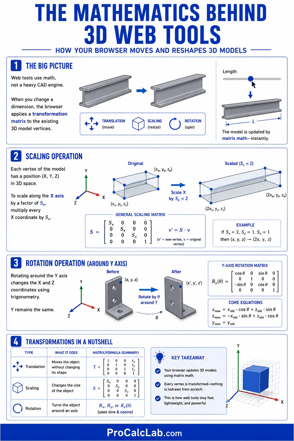
Let us look at a scaling operation. Every corner of our digital beam is defined by a coordinate in 3D space containing an X, a Y, and a Z value. If the user wants to double the length of the beam along the X axis, the software multiplies every X coordinate by a scale factor of 2.
Rotation requires slightly more complex trigonometry. If we want to rotate a structural component around the Y axis, we must calculate new X and Z coordinates for every single point on the model. The core equations for a Y-axis rotation look like this:
Xnew = Xold * cos θ + Zold * sin θ
Znew = -Xold * sin θ + Zold * cos θ
Ynew = Yold
A Practical Matrix Calculation
Let us walk through a concrete example. We have a mounting hole located at an X coordinate of 10 inches and a Z coordinate of 5 inches. The Y coordinate is 0. We need to rotate this hole 90 degrees around the Y axis to align it with a perpendicular bracket.
- Step is determining the trigonometric values for our 90 degree angle. The cosine of 90 degrees is 0. The sine of 90 degrees is 1.
- Step is plugging these values into our X axis equation. We multiply the old X value of 10 by the cosine value of 0, which gives us 0. We then multiply the old Z value of 5 by the sine value of 1, which gives us 5. Adding these together yields a new X coordinate of 5.
- Step is solving the Z axis equation. We multiply the negative old X value of -10 by the sine value of 1, resulting in -10. We multiply the old Z value of 5 by the cosine value of 0, resulting in 0. Adding these together yields a new Z coordinate of -10.
The mounting hole has successfully moved from coordinates 10 and 5 to the new coordinates 5 and -10. A modern web browser performs this exact mathematical operation on 1000000s of vertices 60 times per second to provide a fluid, interactive 3D engineering experience.
Bridging the Gap: Real-Time Structural Validation
While visualizing a model is helpful, the highest value of interactive web tools comes from real-time structural validation. A common mistake during calculations is assuming that a material will hold a load simply because it looks thick enough on the screen. True engineering requires checking the maximum bending moment and the resulting material stress.
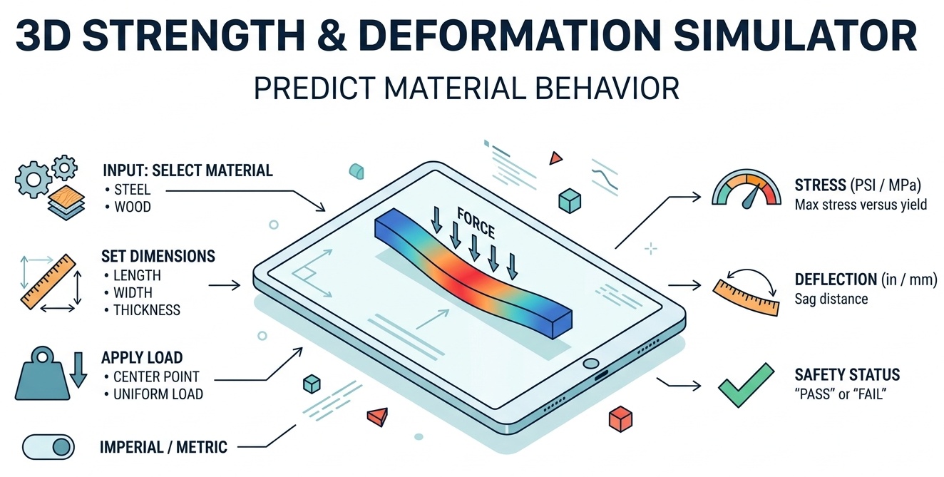
Rather than forcing clients to guess if a custom configuration is structurally sound, developers now embed classical beam theory directly into the web interface. A perfect example of this integration is the Interactive 3D Desk Builder. When a user extends the span of the desk in the browser, the underlying code instantly calculates the new bending moment and deflection based on the selected wood species and thickness. If the user extends the desk past its structural limit, the tool immediately flags the design as unsafe.
The Mathematics of Beam Deflection
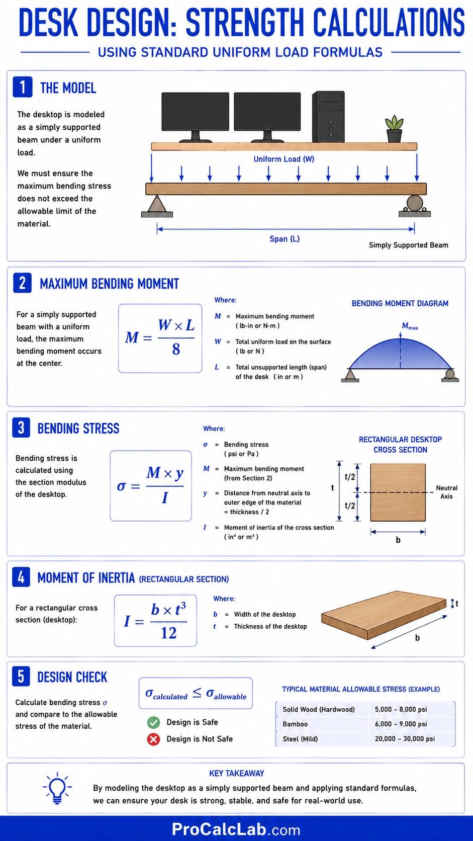
✍ The desk builder utilizes standard uniform load formulas to validate the design. We treat the desktop as a simply supported beam. The most critical factor is the maximum bending stress generated by the load of monitors, computer towers, and the user resting their arms on the surface. We must ensure this stress does not exceed the allowable limits of the material.
The equation for the maximum bending moment of a simply supported beam with a uniform load is:
M = W * L / 8
Where variables are defined as:
- M represents the maximum bending moment.
- W represents the total weight applied to the surface.
- L represents the total unsupported length or span of the desk.
Once we have the bending moment, we calculate the bending stress using the section modulus of the desktop:
σ = M * y / I
Where these variables mean:
- σ is the bending stress.
- y is the distance from the neutral axis to the outer edge of the material. For a solid desktop, this is exactly half the total thickness.
- I is the moment of inertia for a rectangular cross section, calculated as width times thickness cubed, all divided by 12.
A Step-by-Step Desk Calculation
Imagine a user configures a solid oak desktop with a span of 60 inches and a depth of 30 inches. The thickness is 1.5 inches. The total expected load is 200 pounds.
- Step is finding the maximum bending moment. We multiply the 200 pound load by the 60 inch span to get 12000. We divide 12000 by 8 to find our maximum moment. M equals 1500 pound inches.
- Step is determining the moment of inertia. We take the thickness of 1.5 and cube it to get 3.375. We multiply this by the 30 inch depth to get 101.25. We divide by 12 to find our moment of inertia. I equals 8.4375 inches to the 4th power.
- Step is calculating the Y value. Since the total thickness is 1.5 inches, Y is exactly half of that. Y equals 0.75 inches.
- Step is calculating the final bending stress. We multiply the moment of 1500 by the Y value of 0.75 to get 1125. We divide 1125 by the moment of inertia of 8.4375. The final bending stress is 133.33 pounds per square inch.
Since the allowable bending stress for solid oak is roughly 1000 pounds per square inch, the web calculator instantly verifies this configuration as safe and renders the model in green. If the stress exceeded the limit, the tool would demand the user add a center support leg or increase the material thickness.
Standard Reference Data for Web Logic
To program these interactive web simulations accurately, engineers must populate the JavaScript arrays with established material properties. The tables below outline the structural data commonly used to drive the logic behind furniture configurators and architectural span calculators.
Load Capacity Limits Metric
| Material and Thickness | Maximum Span mm | Max Load kg | Deflection Limit mm |
|---|---|---|---|
| Plywood 18 mm | 800 | 45 | 3.0 |
| Solid Oak 25 mm | 1200 | 90 | 4.5 |
| MDF 22 mm | 900 | 40 | 4.0 |
| Solid Walnut 38 mm | 1800 | 150 | 5.5 |
Load Capacity Limits Imperial
| Material and Thickness | Maximum Span inches | Max Load lbs | Deflection Limit inches |
|---|---|---|---|
| Plywood 0.75 in | 32 | 100 | 0.12 |
| Solid Oak 1.00 in | 48 | 200 | 0.18 |
| MDF 0.87 in | 36 | 88 | 0.15 |
| Solid Walnut 1.50 in | 72 | 330 | 0.22 |
Practical Application: The Hybrid Workflow
From a practical standpoint, web-based simulators will not entirely replace heavy desktop CAD software anytime soon. You do not design a 500 part jet engine turbine inside a Chrome browser tab. Desktop systems excel at creating complex initial geometry and running high fidelity finite element analysis.
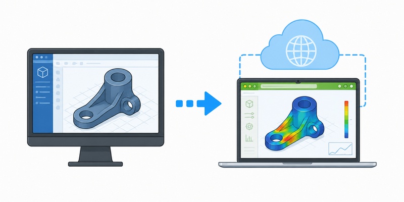
💻 The future is a hybrid digital twin workflow. The senior engineering team designs the core mechanics, the complex extrusions, and the manufacturing tolerances using heavy desktop software. They then extract the parametric rules and export a simplified mesh representation of the product. This lightweight data is fed into a custom web application.
The sales team, the junior engineers, and the end clients use the web application to configure lengths, swap components, and test load scenarios in real time. Once the client approves the interactive web model, the web application sends an API payload back to the desktop CAD server. The CAD server reads the precise coordinates from the payload and automatically generates the final manufacturing drawings and CNC routing paths. This eliminates the tedious back-and-forth iteration cycle completely.
Troubleshooting Web-Based Engineering Tools
Developing these interactive tools introduces unique challenges that traditional mechanical engineers rarely face. When bridging the gap between mechanical design and web development, several critical failure points must be addressed.
Z-Fighting and Clipping Planes
A frequent visual glitch in web-based 3D viewers is Z-fighting. This occurs when 2 distinct faces of a model occupy the exact same coordinate space. Because the web browser uses a finite mathematical precision to determine which face is closer to the camera, it rapidly alternates between rendering the 2 faces as the camera moves. This results in a flickering, broken appearance.
To fix this, engineers must ensure a tiny physical gap exists between mating parts in the exported mesh. A gap of 0.1 millimeters is invisible to the user but completely eliminates the flickering by giving the graphics card a clear depth priority.
Mesh Decimation and Memory Limits
Another major hurdle is polygon count. A highly detailed CAD model of a threaded bolt might contain 50000 individual triangles to perfectly represent the spiral thread. If an assembly contains 100 bolts, the browser will crash trying to load 5000000 polygons into the local memory.
Before moving geometry to the web, the mesh must be aggressively decimated. A bolt head only needs 12 to 24 polygons to look correct on a screen. By stripping out internal components that the user will never see and reducing the resolution of curved surfaces, a 500 megabyte CAD file can be reduced to a 5 megabyte web asset without losing any interactive functionality.
Summary and the Future of Accessible Engineering
The transition from isolated desktop workstations to collaborative web-based simulations represents the democratization of engineering logic. By embedding structural math and spatial transformations directly into the browser, we remove the friction of proprietary software licenses. Clients can instantly interact with digital prototypes, test load capacities, and receive immediate visual feedback on their design choices.
Engineers looking to stay competitive must learn to translate their rigid CAD assemblies into fluid, code-driven web experiences. The ability to program a parametric interface is quickly becoming just as valuable as the ability to draw a perfect schematic.
Literature
To design web tools that comply with modern engineering standards, developers rely on several core texts for both structural formulas and graphics rendering mechanics.
- American Institute of Steel Construction, Steel Construction Manual, 15th Edition. This text provides the foundational load formulas for heavy structural spans.
- Hibbeler, Russell C., Mechanics of Materials, 10th Edition. The definitive guide to calculating bending moments, shear forces, and material stress.
- Matsuda, Kouichi and Lea, Rodger, WebGL Programming Guide. An essential resource for understanding how browsers process 3D matrix math and render polygons.
- Forest Products Laboratory, Wood Handbook: Wood as an Engineering Material. Provides all the baseline yield strengths and modulus of elasticity values required for timber calculators.

David Parry — Senior Engineering Analyst
Specializing in electronics and physics-based simulations with 20+ years of engineering experience. David ensures the mathematical and physical accuracy of the tools at ProCalcLab.