| Status | Waiting... |
| Model Height | 0 mm |
| Print Time | 0h 0m |
| Filament Weight | 0 g |
| Filament Length | 0 m |
| Spool Usage | 0% |
The world of 3D manufacturing moves incredibly fast. For many years, guessing how a digital model would turn into a physical object felt like a gamble. Materials were wasted. Hours were lost on failed prints. Today, the Real-Time 3D Printing Simulator changes the entire workflow. This web-based tool provides a complete visual and mathematical preview of the manufacturing process before the hotend ever heats up. This guide explains exactly how to maximize the potential of this simulator, complete with detailed reference charts, simple mathematical formulas, and practical examples. Download sample 3D model STL file.



Table of Contents
Why Simulation Matters in Modern Manufacturing
Preparation separates successful projects from expensive failures. A visual simulator calculates exactly how the machine will build an object layer by layer. It shows the movement of the print head, estimates the exact amount of plastic required, and calculates the total print time based on specific hardware speeds. This means zero guesswork. Users can adjust settings, swap materials, and instantly see how those choices affect the final product and the production schedule. For businesses managing 10s or 100s of machines, saving 15 minutes per print translates to massive efficiency gains.
How to Use the Simulator
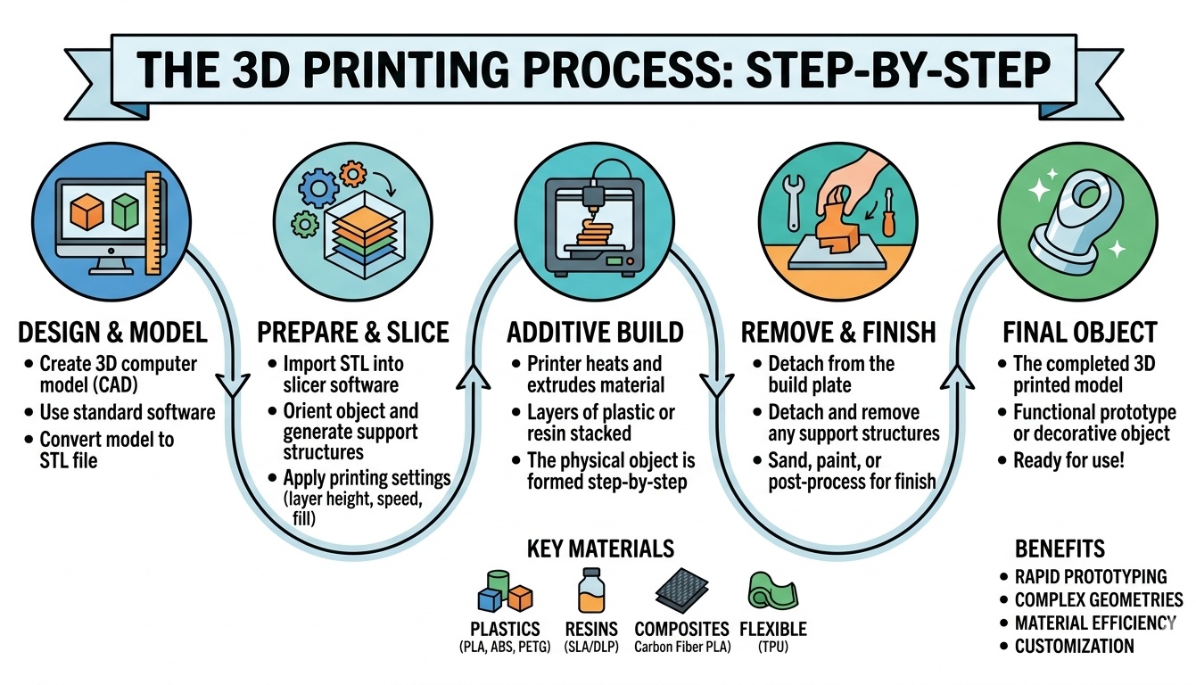
The interface is designed for absolute clarity. Users do not need a degree in mechanical engineering to get accurate results. Follow these 5 simple steps to process any model.
- Step 1: Upload the Model. Click the upload button and select a file. The system accepts standard 3D file formats like STL or GLB. The simulator instantly analyzes the geometry, places it on the virtual build plate, and calculates its physical dimensions.
- Step 2: Select the Color. Use the color picker to match the exact shade of the real filament. This step helps visualize the final product, especially when matching brand colors or aesthetic requirements.
- Step 3: Choose the Material. Select a polymer from the drop-down menu. Options include standard plastics like PLA and industrial-grade materials like Nylon. Selecting a material automatically updates the recommended hardware speed and density factors.
- Step 4: Adjust Infill and Speed. Move the slider to set the internal density of the part. A setting of 10 percent means the object is mostly hollow inside, while 100 percent means it is completely solid plastic. Next, adjust the speed slider to match the physical machine limits.
- Step 5: Run the Simulation. Watch the virtual print head trace the object. The sidebar updates in real-time, showing the current height, elapsed time, and consumed plastic weight. Users can fast-forward the animation by clicking the 10x, 100x, or 1000x speed multipliers.

Understanding Core Printing Materials
Different projects require different polymers. Some parts sit on a desk. Others must survive extreme heat or heavy mechanical stress. The following table provides a comprehensive overview of common materials, their average density, and standard print speeds. The density value is crucial for accurately predicting the final weight of the object.
| Material Type | Density g/cm3 | Standard Speed mm/s | Primary Characteristics and Use Cases | Difficulty Level 1 to 5 |
|---|---|---|---|---|
| PLA | 1.24 | 60 | Easiest to use. Biodegradable. Great for models, prototypes, and decorative items. Melts at low temperatures. | 1 |
| ABS | 1.04 | 50 | Strong and impact-resistant. Used for functional parts. Requires an enclosure to prevent warping. | 3 |
| PETG | 1.27 | 60 | Combines the ease of PLA with the strength of ABS. Excellent layer adhesion and chemical resistance. | 2 |
| TPU | 1.21 | 30 | Highly flexible and rubber-like. Used for phone cases, gaskets, and shock absorbers. Requires slow speeds. | 4 |
| Nylon | 1.08 | 40 | Extremely tough and wear-resistant. Perfect for gears and hinges. Absorbs moisture quickly from the air. | 4 |
| Polycarbonate | 1.20 | 40 | Incredibly strong and heat resistant. Used for bulletproof glass alternatives. Needs extremely high heat. | 5 |
| ASA | 1.07 | 50 | Similar to ABS but highly resistant to ultraviolet light. Perfect for outdoor automotive or garden parts. | 3 |
| HIPS | 1.04 | 50 | Often used as a dissolvable support material for ABS prints. Lightweight and easy to paint. | 3 |
| PVA | 1.19 | 40 | Water-soluble support material. Used alongside PLA for complex geometries with severe overhangs. | 4 |
| Carbon Fiber PLA | 1.30 | 50 | Standard plastic infused with chopped carbon fibers. Highly rigid but abrasive to standard brass nozzles. | 2 |
| Wood Fill | 1.15 | 45 | Plastic mixed with fine wood dust. Smells like wood when heated and can be sanded or stained. | 2 |
| Metal Fill | 2.00 to 4.00 | 40 | Infused with copper, bronze, or steel powders. Extremely heavy. Can be polished to look like solid metal. | 3 |
| PP Polypropylene | 0.90 | 35 | Fatigue resistant. Used for living hinges and food-safe containers. Very difficult to stick to the bed. | 5 |
| PEEK | 1.32 | 25 | Aerospace-grade polymer. Replaces metal parts. Requires specialized industrial machines capable of extreme heat. | 5 |
| Ultem | 1.27 | 30 | High-performance thermoplastic with exceptional flame and heat resistance. Used in medical and aerospace sectors. | 5 |
The Science of Infill: Density Versus Speed
Solid plastic objects take forever to build and consume too much material. To solve this, software generates an internal honeycomb-like structure called infill. By adjusting the percentage, users balance strength, weight, and manufacturing time. The table below illustrates how different infill percentages affect the final product.
| Infill Percentage | Internal Structure | Primary Application | Material Consumption |
|---|---|---|---|
| 10 % | Very sparse lattice. Mostly hollow space. | Visual models, desk toys, and quick dimensional prototypes. | Extremely Low |
| 20 % | Standard density. A good balance of air and plastic. | Everyday prints, standard brackets, and household items. | Low |
| 30 % | Tighter grid. Noticeably stiffer walls. | Parts requiring moderate structural integrity. | Medium |
| 40 % | Dense internal support. Hard to crush by hand. | Mechanical components subject to light stress. | Medium High |
| 50 % | Heavy internal webbing. Thick plastic walls. | Load-bearing brackets and drone frames. | High |
| 60 % | Very dense. The part feels solid to the touch. | Heavy-duty functional parts. | High |
| 70 % | Minimal air gaps remaining. | Industrial jigs and manufacturing fixtures. | Very High |
| 80 % | Almost entirely solid. | High-impact parts like gears and automotive mounts. | Extremely High |
| 90 % | Trace amounts of air gaps for plastic expansion. | Maximum strength requirements short of full solid. | Maximum |
| 100 % | Completely solid block of melted plastic. | Water-tight containers and extreme pressure applications. | Maximum Plus |
Simple Mathematical Estimations
The simulator uses straightforward mathematics to predict outcomes. Understanding these formulas helps users manually verify estimates. No complex symbols are needed.
Bounding Box Volume:
Total Volume = Length multiplied by Width multiplied by Height
Actual Plastic Volume:
Because parts are rarely 100 % solid rectangles, the actual volume of plastic is much smaller. A common estimation is:
Solid Volume = Total Volume multiplied by 0.4 multiplied by a factor of 0.2 plus Infill Percentage multiplied by 0.8
Final Object Weight:
Weight = Solid Volume multiplied by Material Density
Estimated Print Time:
Print Time = Total weight multiplied by an Extrusion Constant divided by Speed Multiplier
Real-World Example Using Imperial Measurements
Let us look at a practical scenario using imperial numbers. A user needs to manufacture a custom electronic housing box. The external dimensions are 6 inches long, 4 inches wide, and 3 inches tall.
First, find the raw volume.
Volume = 6 inches multiplied by 4 inches multiplied by 3 inches = 72 cubic inches.
The user selects ABS plastic. The density of ABS is roughly 0.60 ounces per cubic inch. The infill is set to 20 %. For an electronic box, the actual solid volume of plastic usually equals around 30 percent of the raw bounding box volume due to the hollow interior.
Solid Plastic Volume = 72 cubic inches multiplied by 0.30 = 21.6 cubic inches.
Now, calculate the final weight.
Total Weight = 21.6 cubic inches multiplied by 0.60 ounces per cubic inch = 12.96 ounces.
If the hardware extrudes 0.50 ounces of plastic per hour at the selected speed of 2 inches per second, the time estimate is straightforward.
Print Time = 12.96 ounces divided by 0.50 ounces per hour = 25.92 hours.
The simulator processes these exact steps automatically 100s of times a second to update the display as the user adjusts the sliders.

Troubleshooting Common Simulation and Physical Discrepancies
Sometimes the simulated perfect object does not match the physical result. Physical reality introduces temperature fluctuations and mechanical wear. The following table identifies common defects, their root causes, and how to adjust settings to prevent them.
| Defect Name | Visual Description | Root Cause | Required Solution |
|---|---|---|---|
| Warping | The bottom corners lift off the build plate and curl upward. | Uneven cooling. The top layers shrink faster than the bottom layers. | Increase bed temperature. Use an enclosure to trap heat. Apply adhesive. |
| Stringing | Thin spiderweb-like hairs stretch between gaps in the model. | Plastic oozes out of the nozzle during travel moves across empty space. | Increase retraction distance and retraction speed. Lower nozzle temperature by 5 degrees. |
| Under-extrusion | Gaps, missing layers, or a spongy texture in the walls. | The nozzle is not pushing out enough plastic to form a solid line. | Check for partial nozzle clogs. Increase the extrusion multiplier by 5 percent. Reduce speed. |
| Over-extrusion | Drooping layers, excessive blobs, and dimensional inaccuracy. | The machine pushes too much plastic, causing it to bulge outward. | Lower the extrusion multiplier. Check filament diameter measurements. |
| Layer Shifting | The upper half of the object is offset to the left or right. | The hardware belts skipped a tooth or the motor lost its position. | Tighten mechanical belts. Lower the travel speed. Check motor voltage. |
| Elephant Foot | The very 1st layer bulges outward, wider than the rest of the object. | The nozzle is too close to the bed, squishing the initial plastic too hard. | Raise the Z-offset slightly. Decrease the initial layer bed temperature. |
| Z-Banding | Visible horizontal lines repeating evenly up the sides of the object. | Bent threaded rods or inconsistent extrusion feeding. | Clean and lubricate the vertical lead screws. Check extruder gear tension. |
| Poor Overhangs | Drooping loops of plastic on the underside of angles. | Gravity pulls the hot plastic down before the cooling fan can solidify it. | Increase cooling fan speed to 100 percent. Decrease layer height. Generate support structures. |
| Ghosting | Faint echoes of sharp corners repeating across flat surfaces. | Machine vibrations caused by heavy print heads stopping abruptly. | Reduce printing speed. Reduce acceleration settings. Place the machine on a heavy, stable table. |
| Spaghetti Failure | A massive pile of unattached, tangled plastic lines. | The part detached from the bed mid-print, and the machine kept extruding into the air. | Clean the build plate with alcohol. Improve bed adhesion. Monitor the 1st hour of operation. |
Maximizing Efficiency and Hardware Life
Running hardware at 150 millimeters per second sounds great, but it dramatically increases wear on belts, motors, and bearings. The simulator allows operators to find the golden ratio between speed and time. Bumping the infill down from 30 percent to 20 percent might save 4 hours of machine time without significantly reducing the structural strength of a decorative item. Dropping the speed by 10 millimeters per second might add 1 hour to the clock, but it will eliminate ghosting and improve dimensional accuracy on critical mechanical parts.
👉 Operators should use the visual feedback to check the pathing. If the simulated head spends too much time traveling across open gaps, re-orienting the digital object on the virtual build plate can drastically reduce travel time and stringing issues. The tool eliminates the trial and error phase entirely.
Digital fabrication requires precision. Guessing material weight and operation time is an outdated practice. Utilizing a visual calculation tool ensures that every ounce of polymer is accounted for and every minute of machine time is optimized. By understanding material properties, balancing density settings, and applying simple mathematical validations, anyone can turn digital files into physical reality with complete confidence.
Reference Material
- American Society for Testing and Materials – Standard Guide for Evaluating Mechanical Properties of Materials Made via Additive Manufacturing.
- Polymer Science Dictionary – Thermal properties and density values of commercial thermoplastics.
- Industrial Fabrication Handbook – Speed and feed rate guidelines for Fused Deposition Modeling systems.
- Open Source Hardware Association – Calibration and troubleshooting guidelines for cartesian coordinate robots.

Markus Fletcher — Structural Design Specialist
Expert in structural integrity, 3D modeling, and applied mathematics. Markus focuses on creating precise tools for construction professionals and DIY engineers.