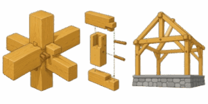
A structural failure in heavy timber construction rarely happens in the middle of a beam. When a roof sags or a frame twists under lateral wind loads, the culprit is almost always the joinery. The nodes where 2 or more timbers meet govern the entire integrity of the structure.

I have seen massive 8-inch by 10-inch Douglas Fir beams rendered structurally useless because the mortise was cut too wide, leaving inadequate edge distance to resist shear tear-out. Engineering a timber frame is not just about sizing members for bending moments; it is about designing connections that manage tension, compression, and shear while accommodating the inevitable dimensional changes of wood.
✍ Unlike steel or concrete, wood is a living, breathing, anisotropic material. Its strength properties change drastically depending on the direction of the grain. If you load a timber parallel to its grain, it acts like a bundle of microscopic carbon-fiber tubes, incredibly strong in compression. If you load it perpendicular to the grain, those same tubes easily crush under the weight. Understanding this directional strength is the foundation of traditional timber framing and log building.
Table of Contents
Mechanics of Wood: An Anisotropic Material
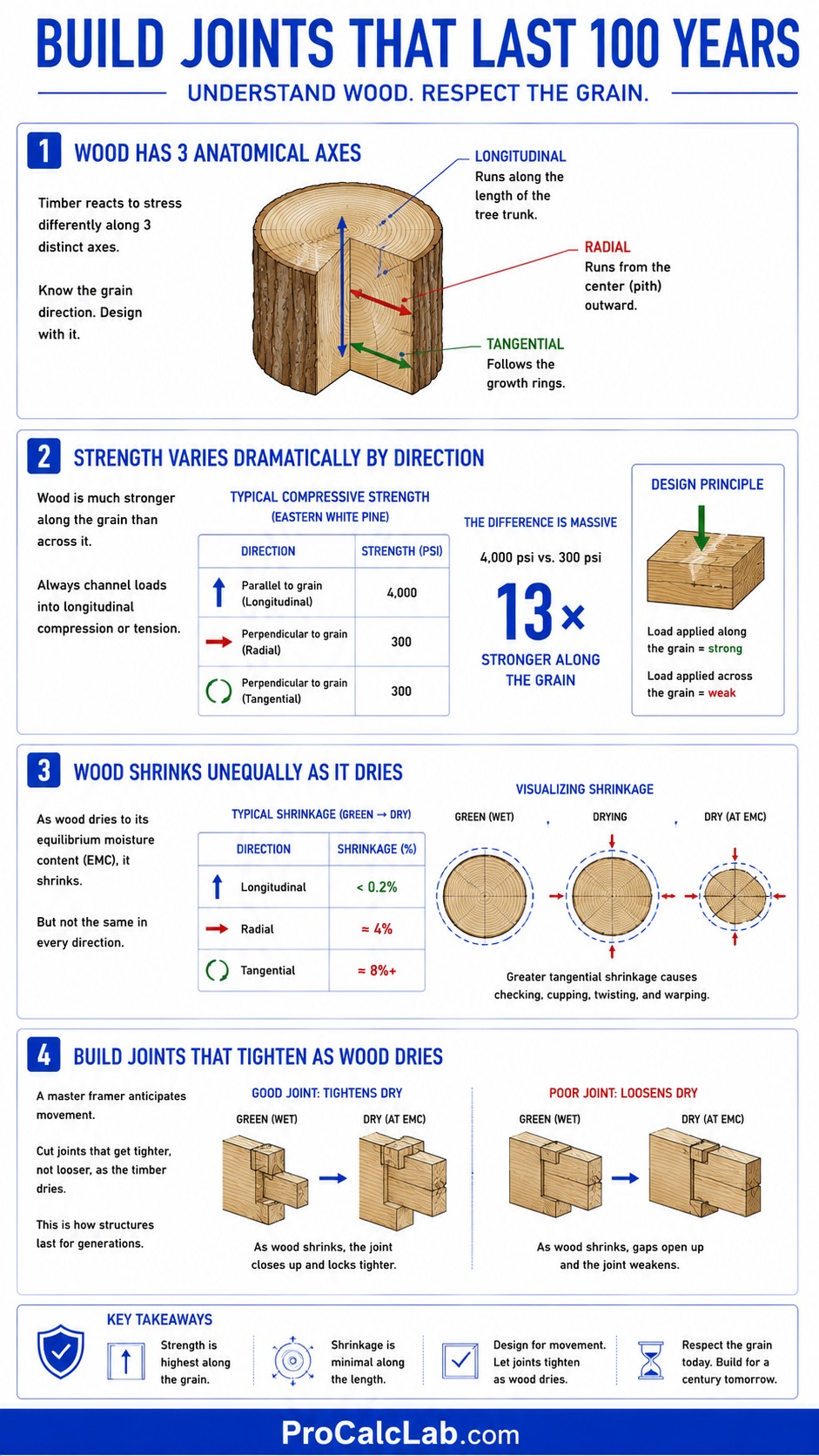
To design a joint that lasts 100 years, you must first understand the cellular structure of wood. Timber reacts to stress across 3 distinct axes: longitudinal, radial, and tangential. The longitudinal axis runs along the length of the tree trunk. The radial axis extends from the center pith outward. The tangential axis follows the circular growth rings.
🏝 Wood is strongest when resisting forces along the longitudinal axis. For a typical species like Eastern White Pine, compressive strength parallel to the grain might reach 4000 psi, while compressive strength perpendicular to the grain maxes out around 300 psi. That is a 13-fold difference. Every joint we carve must channel external loads into longitudinal compression or tension, avoiding perpendicular bearing wherever possible.
Moisture plays an equally critical role. Freshly felled timber, known as green timber, has a high moisture content. As the wood dries to its equilibrium moisture content, it shrinks. However, it does not shrink equally. Longitudinal shrinkage is negligible, usually less than 0.2 %. Radial shrinkage averages 4 %. Tangential shrinkage can exceed 8 %. This unequal shrinkage causes checking and warping. A master framer anticipates this movement and cuts joints that tighten, rather than loosen, as the timber dries.
The Mortise and Tenon: The Workhorse of Timber Framing
The mortise and tenon joint is the fundamental connection in post-and-beam construction. It consists of a projecting tongue, called the tenon, cut into the end of 1 timber, which fits tightly into a corresponding rectangular hole, called the mortise, carved into a second timber. When secured with a hardwood peg, this joint resists tension, compression, and moderate bending moments.
Design Rules for Mortise and Tenon Sizing
In the field, we rely on established proportional rules to prevent localized failure. The thickness of a tenon should generally be 25 % to 33 % of the total thickness of the beam carrying it. If you cut the tenon too thick, the walls of the mortise become dangerously thin and prone to splitting. If you cut the tenon too thin, the tenon itself lacks the shear strength to carry the load.

Consider a standard floor joist tying into a carrying beam. The connection must resist the downward shear force of the floor load. We typically use a housed tenon for this application. A housed tenon features a full-width bearing shoulder that drops into a shallow pocket on the face of the mortised beam. This housing transfers the downward shear load directly across the full width of the timber, relieving the smaller tenon from carrying the entire vertical load.
Draw-Boring: Engineering Pre-Tension into Wood
When you assemble a frame, the joints must remain tight even after the wood shrinks. We achieve this through a technique called draw-boring. Instead of drilling a single straight hole through the assembled joint, we drill the mortise cheeks and the tenon separately, with a deliberate offset.
- Step 1 is drilling the hole through the cheeks of the mortise.
- Step 2 requires inserting the tenon, marking the exact center of the hole onto the tenon cheek, and then removing the tenon.
- Step 3 is drilling the hole through the tenon, but moving the center point exactly 1/8 inch closer to the shoulder of the tenon.
When you reassemble the joint and drive a tapered hardwood peg through the holes, the offset forces the peg to bend through a slight S-curve. This bending acts as a powerful mechanical spring, drawing the shoulder of the tenon tightly against the mortised beam with thousands of pounds of force. As the timbers dry and shrink over the next 5 years, the bent peg maintains this internal tension, preventing the joint from opening.
Traditional Log Construction: The Saddle Notch and Dovetail
🏡 While timber framing relies on point-loaded posts and beams, traditional log construction utilizes continuous horizontal bearing walls. The corners of a log building are the critical nodes. These intersections must lock the walls against lateral wind pressure, resist the outward thrust of the roof, and shed rainwater efficiently.
The half-dovetail notch is a masterpiece of self-locking geometry. The top and bottom faces of the notch slope in 2 different directions. As the massive logs shrink and settle over time, the sloping faces of the dovetail force the joint to wedge itself tighter together. Gravity does the work of maintaining structural integrity.
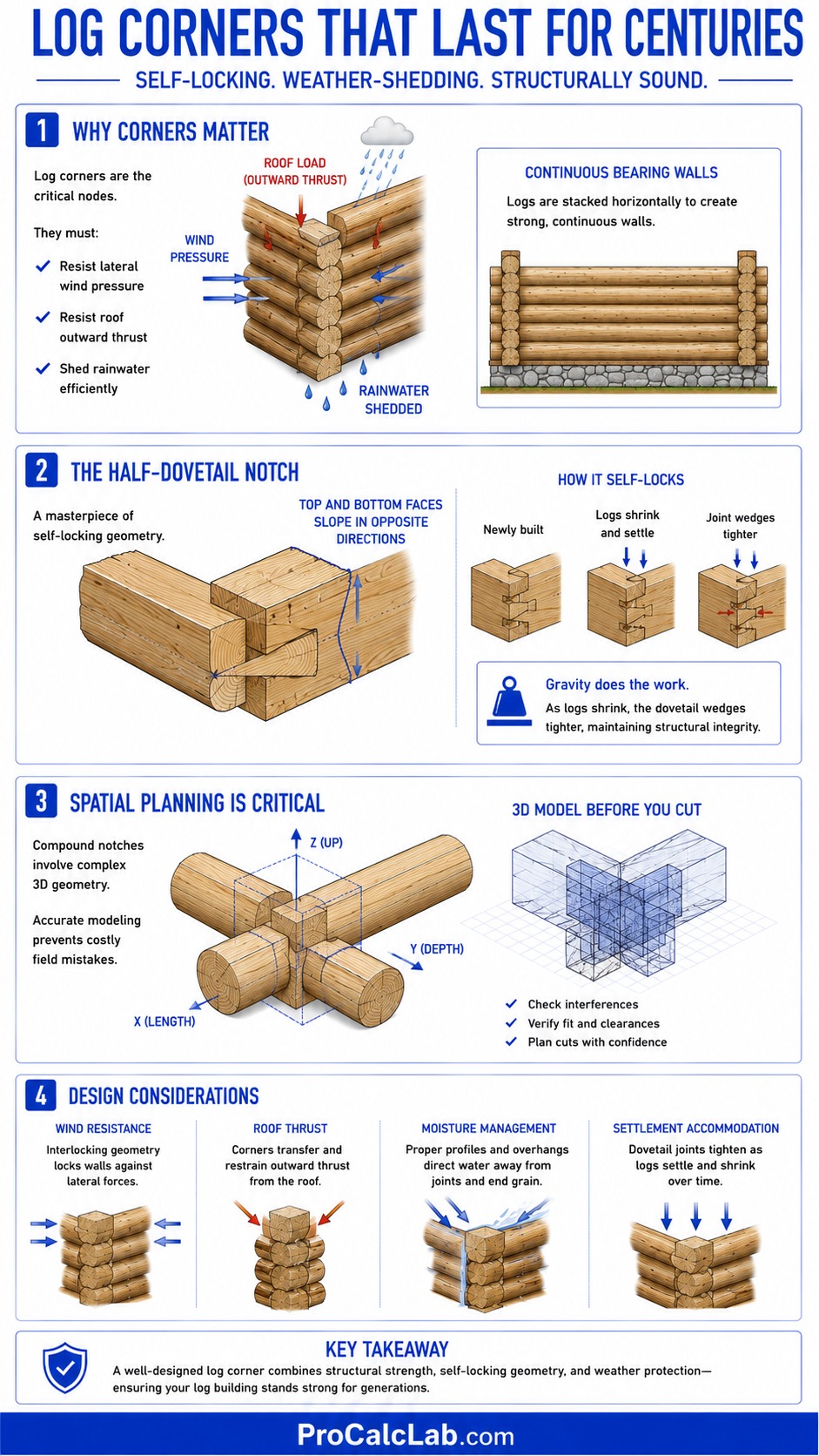
Spatial planning for compound log notches requires rigorous 3D modeling, especially when designing compact, thermally efficient spaces where wall thickness dictates interior volume. When visualizing spatial constraints for a small outdoor structure—which you can experiment with directly in our Sauna 3D Configurator with Blueprints and AR View—the dovetail notch becomes a primary consideration due to its self-locking geometry under thermal cycling. The software allows you to project how intersection geometries impact the overall blueprint, saving countless hours of manual drafting.
Mathematical Modeling of a Pegged Joint
Let us look at the mathematics of a tension joint. When a beam pulls away from a post, the entire load is transferred through the wooden peg. The peg acts like a shear pin. The failure mechanism is typically shear across the 2 planes where the tenon meets the mortise cheeks. This is known as double shear.
The Core Formula
The fundamental equation for determining shear stress on a peg is:
τ = P / (2 * A)
Where variables are defined as:
- τ represents the applied shear stress.
- P represents the total tensile load pulling the joint apart.
- 2 accounts for the 2 shear planes in a standard mortise and tenon.
- A represents the cross-sectional area of the peg.
For a round peg, the area is calculated using:
A = π * r2
A Real-World Calculation Example
Imagine a bottom chord of a roof truss in tension. Wind loads and snow loads generate a tensile pull of 2500 lbs on the joint. We are using a 1-inch diameter White Oak peg. We need to determine if this peg will survive the load without shearing in half.
Step 1 is finding the area of the 1-inch peg. The radius is 0.5 inches.
A = 3.14159 * 0.5 * 0.5
A = 0.785 square inches.
Step 2 is determining the total shear area. Because it is a double shear joint, we multiply the area by 2.
Total Shear Area = 1.57 square inches.
Step 3 is calculating the applied shear stress.
τ = 2500 lbs / 1.57 square inches
τ = 1592 psi.
Step 4 is comparing the applied stress against the allowable design value. White Oak has an ultimate shear strength parallel to the grain of roughly 2000 psi. With safety factors applied by building codes, the allowable shear might be reduced to around 1700 psi. Our applied stress of 1592 psi is less than the allowable 1700 psi. The 1-inch peg will safely hold the load, though a conservative engineer might specify a 1.25-inch peg to increase the safety margin.
Material Properties and Design Values
Selecting the right timber species is just as important as cutting the joint correctly. Hardwoods offer incredible shear strength for pegs and splines, while softwoods provide excellent strength-to-weight ratios for long-spanning beams. The tables below outline the mechanical properties of common structural timbers used in heavy framing. Note that these are baseline values for clear, straight-grained wood at 12 % moisture content.
Mechanical Properties of Structural Timber Metric
| Wood Species | Compressive Strength Parallel MPa | Shear Strength Parallel MPa |
|---|---|---|
| Douglas Fir | 50.0 | 6.2 |
| Eastern White Pine | 33.1 | 4.7 |
| White Oak | 51.3 | 13.8 |
| Western Red Cedar | 31.5 | 5.4 |
| Southern Yellow Pine | 54.6 | 9.5 |
Mechanical Properties of Structural Timber Imperial
| Wood Species | Compressive Strength Parallel psi | Shear Strength Parallel psi |
|---|---|---|
| Douglas Fir | 7250 | 900 |
| Eastern White Pine | 4800 | 680 |
| White Oak | 7440 | 2000 |
| Western Red Cedar | 4560 | 780 |
| Southern Yellow Pine | 7920 | 1380 |
Troubleshooting Common Joint Failures
From a practical standpoint, errors in timber framing multiply. A gap of 1/16 inch at the shoulder of a joint might seem acceptable during shop assembly. But when that beam spans 16 feet, that tiny gap allows the beam to rotate, translating into a roof deflection of over 1 inch. Precision at the node dictates stability across the span.
Relishing and Shear Tear-Out
A frequent error among novice builders is insufficient relish. Relish is the amount of solid wood left on the tenon past the peg hole. If the peg hole is drilled too close to the end of the tenon, the tensile load will simply rip the end of the tenon right off. The wood shears along the grain line. As a strict rule, the relish distance must be at least 3 times the diameter of the peg. If you use a 1-inch peg, you need a minimum of 3 inches of solid wood past the edge of the hole.
Compression Perpendicular to Grain Crushing
I frequently inspect historic barns where the floor beams meet the sill plates. Often, the sill plates are severely crushed directly beneath the posts. This happens when the vertical load of the roof is transferred onto the horizontal grain of the sill plate, exceeding the perpendicular compressive strength of the wood. Modern engineering corrects this by bringing the post down all the way to the foundation, bypassing the horizontal sill timber completely, or by using metal bearing plates to distribute the load over a wider area.
Advanced Joinery: Splicing Timbers with Scarf Joints
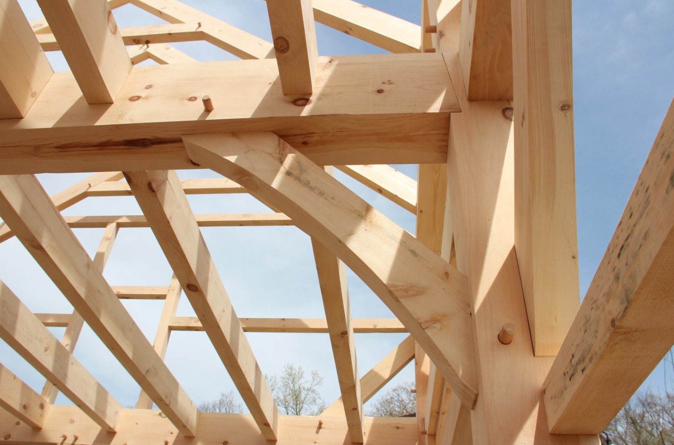
When a building design requires a continuous beam that is longer than the available logs, we must splice 2 timbers together end-to-end. This is achieved using a scarf joint. A simple butt joint would instantly fail under bending loads. A scarf joint overlaps the timbers, utilizing a combination of interlocking angles, wedges, and pegs to maintain structural continuity.
The stop-splayed scarf with under-squinted butts is a pinnacle of timber engineering. The splayed angle provides a long gluing and bearing surface. The under-squinted butts lock the timbers mechanically, preventing them from pulling apart longitudinally. Hardwood wedges, known as folding wedges, are driven into the center of the joint to force the mating surfaces tightly against each other.
A common mistake during calculations is placing a scarf joint in the middle of a beam span. The middle of a span is the point of maximum bending moment. A scarf joint, no matter how perfectly cut, is never as strong as an unbroken beam. Engineers always place scarf joints above bracing struts or near support posts, targeting the points of inflection where the bending moment drops to 0.
Final Thoughts and Modern Integration
Engineering a timber frame or log structure requires a deep respect for the physical limitations and natural movement of wood. While we now have access to computer numeric control routers and laser leveling systems, the foundational physics of the mortise, tenon, and dovetail remain unchanged. A well-engineered joint manages shear, balances compression, and anticipates the inevitable shrinkage of the timber over decades of service.
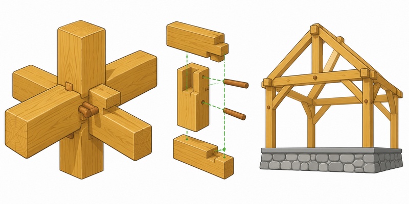
Today, we combine these ancient techniques with modern structural analysis. We apply exact yield equations to our peg diameters, model the thermal dynamics of our log walls, and calculate precise deflection limits for our floor systems. The beauty of timber framing is not just in its aesthetic appeal, but in its profound structural honesty. Every peg, housing, and notch serves a specific, calculated mathematical purpose.
Literature
To design structures that comply with modern building codes while utilizing traditional methods, engineers rely on several core texts and standards. The mathematics and yield equations used to verify these joints are derived from extensive laboratory testing.
- American Wood Council, National Design Specification for Wood Construction, 2018 Edition.
- Forest Products Laboratory, Wood Handbook: Wood as an Engineering Material, Centennial Edition.
- Timber Framers Guild, Timber Framing Fundamentals, 1st Edition.
- Benson, Tedd, Building the Timber Frame House: The Revival of a Forgotten Craft.

David Parry — Senior Engineering Analyst
Specializing in electronics and physics-based simulations with 20+ years of engineering experience. David ensures the mathematical and physical accuracy of the tools at ProCalcLab.