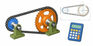
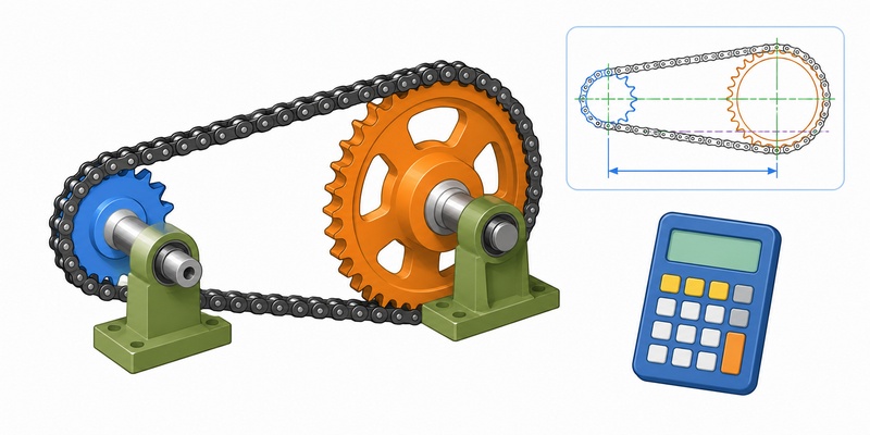
Mechanical power transmission requires precision. Getting the sprockets, chain pitch, and center distance wrong leads to premature wear, skipped teeth, and mechanical failure. This 3D chain drive designer eliminates the guesswork and provides a clear visual representation of the final assembly. Builders, engineers, and hobbyists can model drivetrains before cutting steel or ordering parts.



This guide explains how to use the calculator, covers core principles of power transmission, and provides extensive reference tables for standard sizes, speed ratios, and torque calculations.
Table of Contents
How to Use This Calculator
The interface relies on a few fundamental inputs to generate the 3D model and calculate physical dimensions. Enter the precise parameters of the planned drive system to see real-time updates.
Step 1: Set the Chain Pitch
Pitch is the exact distance between two consecutive roller pins. This value determines the physical scale of the entire drivetrain. Entering the correct pitch ensures the sprockets are scaled accurately in the 3D space. Refer to the standard sizing tables below to find the correct decimal value for specific chains.
Step 2: Enter Sprocket Tooth Counts
The system requires the number of teeth for both the drive sprocket and the driven sprocket. The drive sprocket connects to the power source like a motor or engine. The driven sprocket mounts to the axle or wheel being turned. The ratio between these two numbers dictates the final speed and torque output.
Step 3: Define the Center Distance
Center distance is the straight-line measurement from the center point of the drive shaft to the center point of the driven shaft. The calculator uses this exact value along with the tooth counts to determine the total required chain length. The 3D view will space the sprockets apart based on this input.
Step 4: Interact with the 3D Model
Once parameters are entered, rotate and zoom the 3D view. This helps verify that the relative sizes of the sprockets look correct and that the chain path makes sense for the intended application. Visualizing the layout prevents clearance issues where a massive driven sprocket might hit the ground or a frame component.
Understanding Roller Chain Standards
Roller chains follow strict international standards to ensure compatibility across manufacturers. The two most common standards are ANSI for North America and ISO or British Standard for Europe and Asia. The identification numbers stamped on the side plates indicate the physical dimensions.
ANSI Roller Chain Dimensions
ANSI chain numbers follow a logical rule. The first digit or two digits indicate the pitch in eighths of an inch. A final digit of 0 means standard roller width, while a 5 means a narrow roller. A 1 indicates a lightweight chain.
| ANSI Number | Pitch, in / mm | Roller Width, in / mm | Roller Diameter, in / mm |
|---|---|---|---|
| 25 | 1/4 / 6.35 | 1/8 / 3.18 | 0.13 / 3.30 |
| 35 | 3/8 / 9.53 | 3/16 / 4.76 | 0.20 / 5.08 |
| 40 | 1/2 / 12.7 | 5/16 / 7.95 | 0.31 / 7.92 |
| 41 | 1/2 / 12.7 | 1/4 / 6.35 | 0.31 / 7.77 |
| 50 | 5/8 / 15.88 | 3/8 / 9.53 | 0.40 / 10.16 |
| 60 | 3/4 / 19.05 | 1/2 / 12.7 | 0.47 / 11.91 |
| 80 | 1 / 25.4 | 5/8 / 15.88 | 0.63 / 15.88 |
| 100 | 1.25 / 31.75 | 3/4 / 19.05 | 0.75 / 19.05 |
| 120 | 1.5 / 38.1 | 1 / 25.4 | 0.88 / 22.23 |
| 140 | 1.75 / 44.45 | 1.13 / 28.58 | 1.00 / 25.4 |
| 160 | 2 / 50.8 | 1.25 / 31.75 | 1.13 / 28.58 |
British Standard and ISO Dimensions
The ISO standard uses sixteenths of an inch for the pitch measurement, followed by the letter B.
| ISO Number | Pitch, in / mm | Roller Width, in / mm | Roller Diameter, in / mm |
|---|---|---|---|
| 04B | 1/4 / 6.35 | 0.11 / 2.80 | 0.16 / 4.00 |
| 06B | 3/8 / 9.53 | 0.22 / 5.72 | 0.25 / 6.35 |
| 08B | 1/2 / 12.7 | 0.31 / 7.75 | 0.33 / 8.51 |
| 10B | 5/8 / 15.88 | 0.38 / 9.65 | 0.40 / 10.16 |
| 12B | 3/4 / 19.05 | 0.46 / 11.68 | 0.48 / 12.07 |
| 16B | 1 / 25.4 | 0.67 / 17.02 | 0.62 / 15.88 |
| 20B | 1.25 / 31.75 | 0.77 / 19.56 | 0.75 / 19.05 |
| 24B | 1.5 / 38.1 | 1 / 25.4 | 1.00 / 25.4 |
Motorcycle and ATV Chain Sizes
Motorcycles utilize a specific sizing system based on eighths of an inch. The first digit represents the pitch, while the remaining digits describe the internal width.
| Motorcycle Number | Pitch, in / mm | Roller Width, in / mm |
|---|---|---|
| 415 | 1/2 / 12.7 | 3/16 / 4.76 |
| 420 | 1/2 / 12.7 | 1/4 / 6.35 |
| 428 | 1/2 / 12.7 | 5/16 / 7.94 |
| 520 | 5/8 / 15.88 | 1/4 / 6.35 |
| 525 | 5/8 / 15.88 | 5/16 / 7.94 |
| 530 | 5/8 / 15.88 | 3/8 / 9.53 |
| 630 | 3/4 / 19.05 | 3/8 / 9.53 |
Speed Ratios and Torque Multiplication
The speed ratio dictates how rotational speed and twisting force transfer from the engine to the wheels or output shaft. A large ratio means high torque and low top speed. A small ratio means low torque but high top speed. Selecting the right combination of teeth is the most critical design choice.
✍ To find the ratio, simply divide the number of teeth on the driven sprocket by the number of teeth on the drive sprocket. A ratio of 3.0 means the drive sprocket turns three times for every one complete revolution of the driven sprocket.
Common Speed Ratio Lookup Table
This table covers standard sprocket combinations for light vehicles, conveyors, and industrial equipment. Drive sprockets are listed across the top, driven sprockets down the left side.
| Driven Teeth | 10T Drive | 12T Drive | 15T Drive | 18T Drive | 20T Drive |
|---|---|---|---|---|---|
| 30T | 3.00 | 2.50 | 2.00 | 1.67 | 1.50 |
| 36T | 3.60 | 3.00 | 2.40 | 2.00 | 1.80 |
| 40T | 4.00 | 3.33 | 2.67 | 2.22 | 2.00 |
| 45T | 4.50 | 3.75 | 3.00 | 2.50 | 2.25 |
| 50T | 5.00 | 4.17 | 3.33 | 2.78 | 2.50 |
| 54T | 5.40 | 4.50 | 3.60 | 3.00 | 2.70 |
| 60T | 6.00 | 5.00 | 4.00 | 3.33 | 3.00 |
| 66T | 6.60 | 5.50 | 4.40 | 3.67 | 3.30 |
| 72T | 7.20 | 6.00 | 4.80 | 4.00 | 3.60 |
| 80T | 8.00 | 6.67 | 5.33 | 4.44 | 4.00 |
Formulas for Manual Calculation
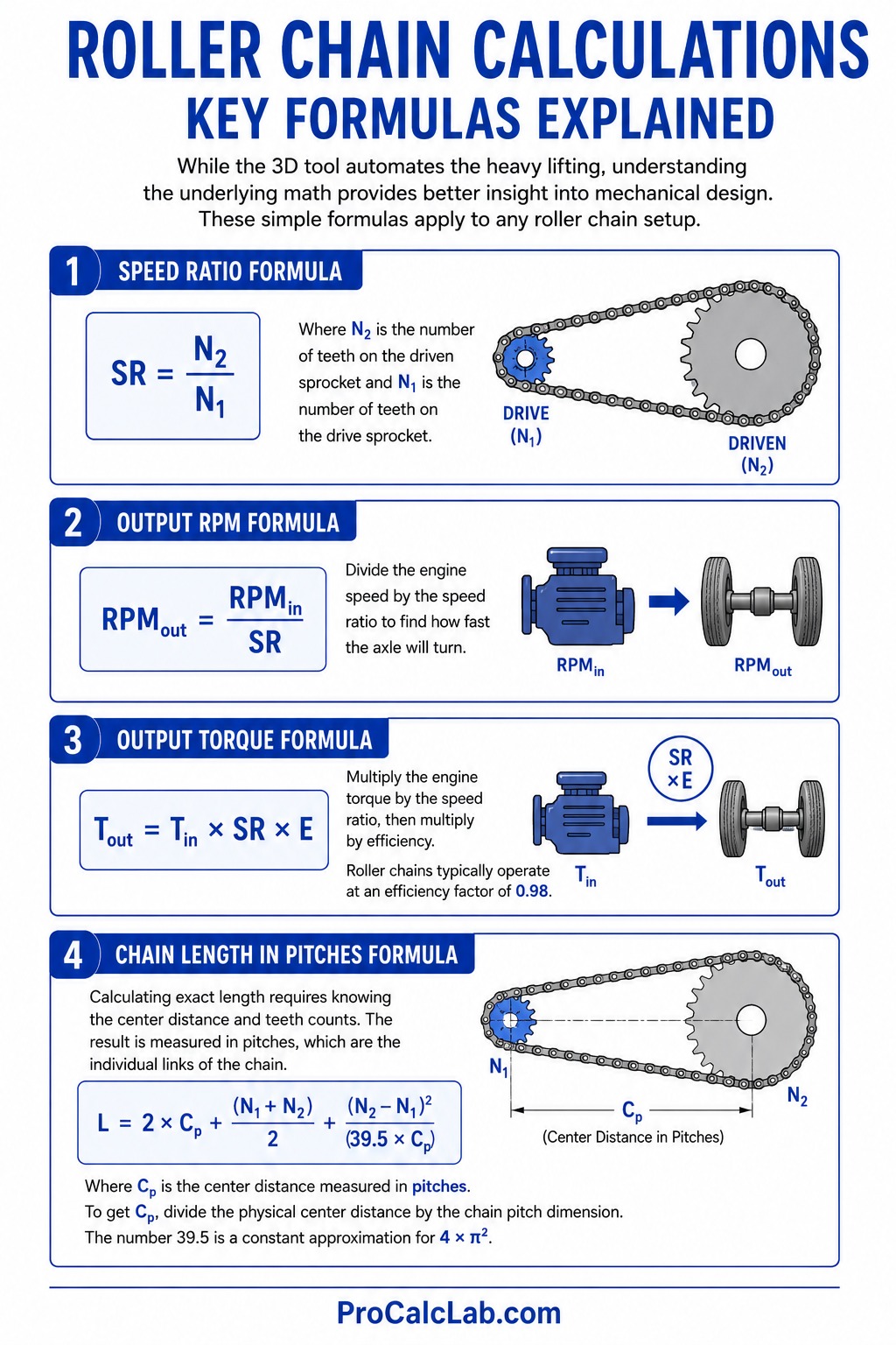
While the 3D tool automates the heavy lifting, understanding the underlying math provides better insight into mechanical design. These simple formulas apply to any roller chain setup.
Speed Ratio Formula
SR = N2 / N1
Where N2 is the number of teeth on the driven sprocket and N1 is the number of teeth on the drive sprocket.
Output RPM Formula
RPMout = RPMin / SR
Divide the engine speed by the speed ratio to find how fast the axle will turn.
Output Torque Formula
Tout = Tin * SR * E
Multiply the engine torque by the speed ratio, then multiply by efficiency. Roller chains typically operate at an efficiency factor of 0.98.
Chain Length in Pitches Formula
Calculating exact length requires knowing the center distance and teeth counts. The result is measured in pitches, which are the individual links of the chain.
L = 2 * Cp + (N1 + N2) / 2 + (N2 – N1)2 / (39.5 * Cp)
Where Cp is the center distance measured in pitches. To get Cp, divide the physical center distance by the chain pitch dimension. The number 39.5 is a constant approximation for 4 * π2.
Practical Design Example
Let us walk through a complete design for a standard recreational vehicle, applying all the rules and formulas.
Application: Small off-road buggy.
Power Source: Small engine with a peak torque of 10 ft-lbs at 3600 RPM.
Drive Sprocket: 12 teeth clutch.
Driven Sprocket: 60 teeth axle sprocket.
Center Distance: 16 inches exact measurement from shaft to shaft.
Chain Size: Number 40 ANSI chain. The pitch is 0.5 inches.
First, calculate the speed ratio. Divide the 60 teeth by the 12 teeth to get a ratio of 5. This means the axle will turn one fifth the speed of the engine, but with nearly five times the twisting force.
Next, find the output RPM at top engine speed. Divide 3600 by 5 to get 720 RPM at the axle.
Calculate the estimated output torque. Multiply the 10 ft-lbs input torque by the 5 ratio, giving 50 ft-lbs. Factoring in a 2 % efficiency loss, the true final torque is 49 ft-lbs.
Now determine the required chain length. We must convert the 16-inch center distance into pitches. Divide 16 by the 0.5 inch pitch, which equals 32 pitches. Now plug the values into the length formula:
L = 2 * 32 + (12 + 60) / 2 + (60 – 12)2 / (39.5 * 32)
L = 64 + 36 + 2304 / 1264
L = 100 + 1.82 = 101.82 pitches.
🚲 A chain must form a closed loop, so you cannot buy fractions of a link. Furthermore, chains require an even number of pitches unless a half-link offset is used, which weakens the assembly. Always round up to the nearest even whole number. The required chain length is exactly 102 pitches.
To find the physical length of the chain, multiply 102 pitches by the 0.5 inch pitch size. The total unrolled length of the chain is 51 inches.
Center Distance and Sprocket Placement Best Practices
Selecting the distance between shafts is not arbitrary. Poor placement causes chain slap, binding, and rapid sprocket wear. Follow these mechanical guidelines when designing the frame or mounting plates.
- Minimum Distance: The center distance must be strictly greater than one half the sum of the sprocket outside diameters. If it is shorter, the sprocket teeth will physically grind against each other.
- Ideal Distance: Engineers generally target a distance equal to 30 to 50 times the chain pitch. For a half-inch pitch chain, an ideal distance is between 15 and 25 inches.
- Maximum Distance: Avoid distances greater than 80 times the pitch. Extremely long chains experience excessive weight-induced sag and require bulky idler tensioners to prevent them from jumping off the teeth.
- Wrap Angle: The chain must wrap around the smaller drive sprocket enough to grip the teeth. Aim for a minimum wrap angle of 120 degrees. Small sprockets placed too close to massive driven sprockets will have a poor wrap angle and slip under heavy loads.
The Polygonal Effect and Chordal Action
A sprocket is not a perfect circle. It is a polygon where each flat side equals one chain pitch. When the chain engages the sprocket, it rises and falls slightly as it navigates the points of the polygon. This vertical bumping is called chordal action.
Chordal action creates harsh vibrations and cyclical speed variations. Using sprockets with very few teeth makes the polygon effect extreme. A 9-tooth sprocket operates like a bumpy nonagon, violently jerking the chain. This is why drive sprockets should ideally have 15 or more teeth for smooth operation. Small 10-tooth sprockets work for low speeds but will destroy chains quickly at high RPM due to the harsh impact forces.
Idler Sprockets and Chain Tension
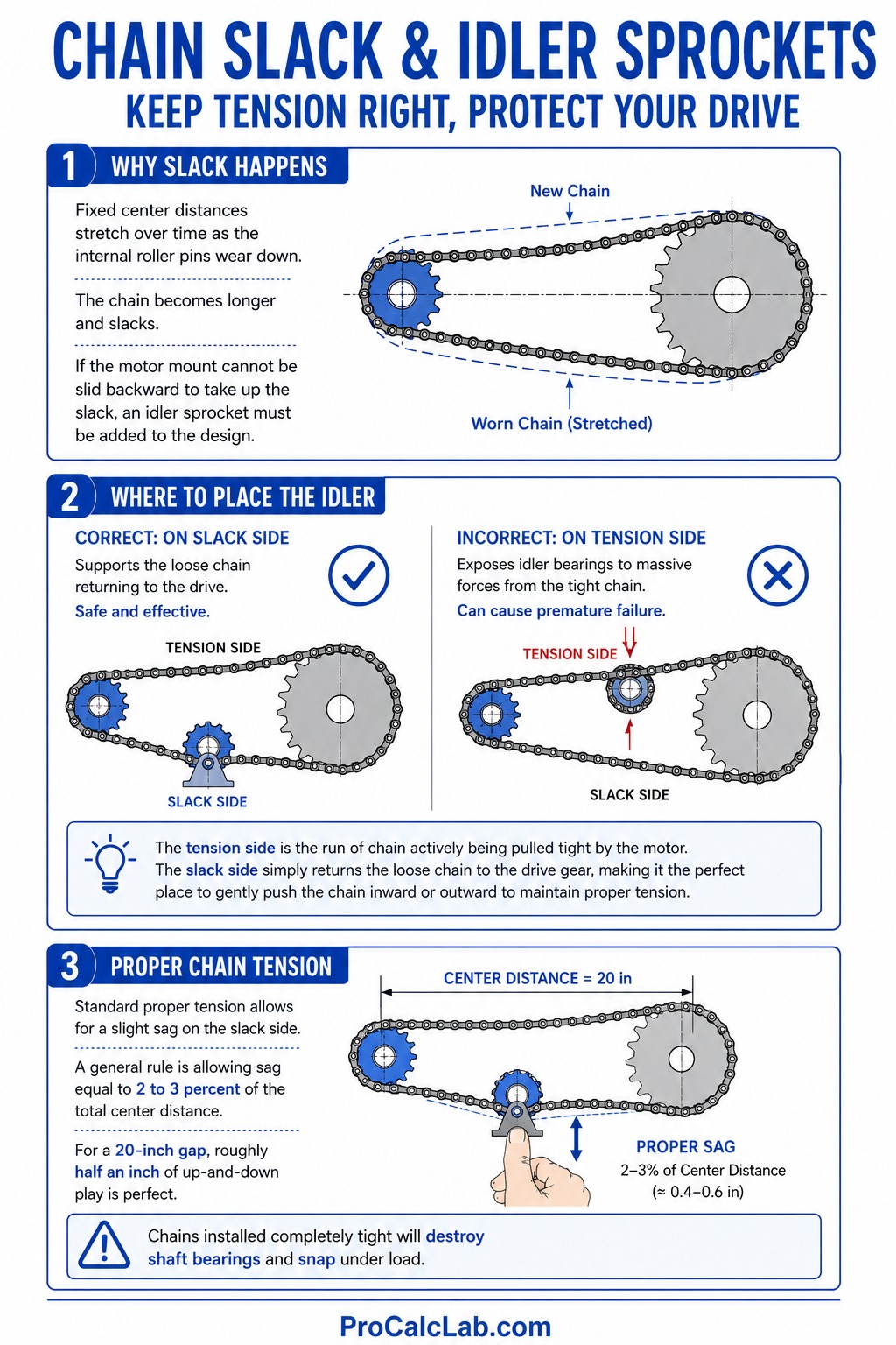
Fixed center distances stretch over time as the internal roller pins wear down. The chain becomes longer and slacks. If the motor mount cannot be slid backward to take up the slack, an idler sprocket must be added to the design.
⚙ Mount the idler sprocket on the slack side of the chain loop, not the tension side. The tension side is the run of chain actively being pulled tight by the motor. Placing an idler on the tight side exposes the idler bearings to massive destructive forces. The slack side simply returns the loose chain to the drive gear, making it the perfect place to gently push the chain inward or outward to maintain proper tension.
Standard proper tension allows for a slight sag on the slack side. A general rule is allowing sag equal to 2 to 3 % of the total center distance. For a 20-inch gap, roughly half an inch of up-and-down play is perfect. Chains installed completely tight will destroy shaft bearings and snap under load.
Lubrication and Maintenance
Steel sliding against steel under extreme pressure generates massive heat and friction. Without a microscopic layer of oil, the pins and bushings will grind each other into dust. The method of oil delivery depends strictly on the speed of the chain.
| Speed Range, ft/min | Lubrication Method | Description |
|---|---|---|
| Under 150 | Manual Application | Oil is periodically brushed or sprayed onto the slack side. Suitable for slow conveyors or bicycles. |
| 150 to 1500 | Drip Feed | An oil reservoir slowly drips lubrication directly onto the link edges as they pass. |
| 1500 to 2500 | Oil Bath | The lowest point of the chain dips into a sealed sump of oil, carrying it upward to the rest of the drive. |
| Over 2500 | Pumped Stream | A pressurized pump sprays a continuous stream of oil directly onto the inner plates to cool and lubricate the assembly. Required for high-RPM industrial machinery. |
A common misconception is that grease is an excellent chain lubricant. Heavy grease coats the outside but fails to penetrate the tiny gaps between the pins and inner plates where the actual friction occurs. Use dedicated foaming chain lubes or gear oil that wicks inward before thickening.
Identifying Common Failure Modes
Even perfectly designed systems eventually fail. Reading the wear patterns reveals flaws in the initial math or installation alignment.
- Tensile Breakage: The side plates physically snap in half. This means the engine torque drastically exceeded the ultimate tensile strength rating of the chosen chain size. The solution is moving to a heavier pitch or using double-strand roller chain.
- Pin Galling: The pins turn blue or black from extreme heat and seize solid. This happens when the chain is run at high speeds with zero lubrication.
- Sprocket Hooking: The teeth of the sprocket begin to lean over and look like sharp hooks or circular saw blades. This indicates extreme age or abrasive dirt grinding away the steel. Once hooking occurs, the sprocket must be replaced. Putting a new chain on hooked sprockets will ruin the new chain immediately.
- Excessive Elongation: The chain seems to have stretched several inches. Steel side plates do not actually stretch like rubber under normal loads. Instead, the internal pins have worn down, creating microscopic extra space at every single joint. Across 100 links, this tiny wear adds up to a visibly longer chain. Elongation past 3 % requires immediate replacement.
- Side Plate Scuffing: The inner faces of the plates are ground shiny and thin. This proves the drive and driven sprockets are not perfectly parallel. Misalignment forces the chain to scrape against the sprocket faces diagonally. Realign the shafts immediately.
Materials and Tensile Strength
Not all chains are identical just because they share the same pitch size. The steel alloy and heat treatment process determine the load capacity.
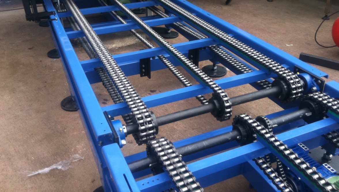
Standard carbon steel chains handle the majority of mechanical tasks. Nickel-plated chains resist rust in damp outdoor conditions but offer no extra physical strength. Stainless steel chains are utilized in food processing and highly corrosive chemical environments. However, stainless steel is significantly softer than hardened carbon steel, reducing its overall load capacity and tensile strength by almost half.
🏎 For high-horsepower racing applications, heavy-duty chains feature thicker side plates and solid forged rollers rather than split, rolled sheet metal. These O-ring or X-ring chains contain tiny rubber seals that trap factory grease directly inside the pin joints, drastically extending lifespan in abrasive dirt environments at the cost of slightly higher friction resistance.
Summary for Builders
Always input accurate pitch and tooth counts into the 3D designer tool to visualize the exact layout. Keep center distances within the recommended limits, avoid 10-tooth drive sprockets when high speeds are involved, and remember to round up your final chain length calculations to an even number of links. Maintain slight slack in the system and lubricate often to ensure a long operating life.
References
- Machinery’s Handbook, 31st Edition. Industrial Press. Power Transmission and Chain Sizing.
- American National Standards Institute. ANSI B29.1 Precision Power Transmission Roller Chains.
- International Organization for Standardization. ISO 606 Short-pitch transmission precision roller and bush chains.

David Parry — Senior Engineering Analyst
Specializing in electronics and physics-based simulations with 20+ years of engineering experience. David ensures the mathematical and physical accuracy of the tools at ProCalcLab.