| Excavation | — |
| Usable Vol | — |
| Concrete | — |
| Rebar Mesh | — |
| Waterproofing | — |
| XPS Insul. | — |
| Ground Press. | — |
Planning an underground storage structure requires precision and careful consideration of soil mechanics and material properties. The 3D Cellar Builder And Estimator is an interactive tool designed to help builders and property owners visualize their project and calculate accurate material requirements. This guide explains how to operate the interface and interpret the structural data it provides.


Navigating The Interface Controls
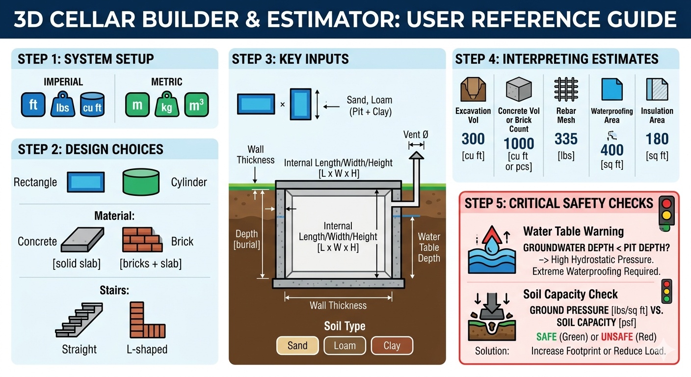
The tool features a top control panel with several toggle buttons. These buttons change the fundamental geometry and structural assumptions of the 3D model. Selecting different options instantly updates the visual rendering and the material estimates.
Shape Selection
The tool offers 2 primary shapes. The Rectangle option creates a standard 4-sided room. This layout maximizes interior wall space for shelving and is standard for most residential builds. The Cylinder option creates a circular shaft. Cylindrical structures naturally resist lateral soil pressure better than flat walls, making them highly efficient for deep installations, though shelving requires custom curved construction.
Material Selection
Builders can choose between 2 structural materials. The Concrete option assumes the walls, floor, and roof are poured as solid reinforced monolithic slabs. The Brick option calculates requirements for standard masonry walls while maintaining a concrete floor and a concrete roof slab. Poured concrete generally provides superior waterproofing out of the ground, while brick offers an easier installation process for locations where heavy concrete trucks cannot access the site.
Stair Configuration
Access to the underground space requires a safe descent. The Straight option models a single uninterrupted flight of steps. This requires a longer horizontal footprint. The L-shaped option introduces a landing platform halfway down and turns the path 90 degrees. This configuration saves linear space and fits better into compact footprints.
System Of Measurement
The calculator supports 2 distinct measurement systems. Toggling between Imperial and Metric automatically converts all slider limits and output values. Imperial operates in feet, inches, pounds, and square feet. Metric operates in meters, millimeters, kilograms, and square meters.
Soil Type Selection
Selecting the correct soil type is crucial for structural safety. The tool provides 3 broad categories. Sand represents loose, granular soils with excellent drainage but poor cohesion. Loam represents a balanced agricultural soil with moderate bearing capacity. Clay represents dense, cohesive soils that hold water and exert extreme lateral pressure when wet. Changing the soil type directly impacts the ground pressure limits displayed in the results panel.

Table of Contents
Adjusting Dimensional Parameters
The input section consists of several sliders and text fields. Users can drag the slider for visual adjustments or type specific numbers directly into the input boxes for exact calculations.
- Length and Width: These represent the internal usable dimensions of the room. For cylindrical structures, the Length input changes to represent the internal diameter.
- Height: This represents the internal vertical clearance from the finished floor to the ceiling. A standard comfortable height is usually 7 feet or 2.1 meters.
- Wall Thickness: This defines the structural mass of the exterior shell. Deeper structures require thicker walls to withstand lateral earth pressure.
- Depth: This measures how far the interior floor surface sits below the surrounding exterior ground level. A structure can be fully buried or partially raised above grade.
- Water Table: This indicates the depth at which groundwater sits. If the water table is shallower than the excavation depth, the structure will sit in water and require extreme waterproofing measures.
- Vent Diameter: Proper airflow prevents mold. This sets the size of the required intake and exhaust pipes. Standard natural draft systems use 4-inch or 6-inch pipes.
Interpreting The Calculation Results
The results panel provides 7 specific data points vital for project budgeting and site preparation.
Excavation Volume
This is the total amount of earth that must be removed from the ground. The calculator automatically adds an over-dig working gap around the outer perimeter. In Imperial mode, it adds 1.5 feet of clearance. In Metric mode, it adds 0.5 meters. This space is mandatory for workers to apply external waterproofing and install drainage pipes before backfilling.
Usable Volume
This represents the pure internal air space. It helps determine the capacity for storage and allows HVAC engineers to calculate the required air exchange rates for ventilation fans.
Material Estimates
If Concrete is selected, this row displays the total cubic volume of wet concrete needed for the entire shell. If Brick is selected, the tool splits the result into 2 numbers. It provides the exact count of standard masonry bricks needed for the vertical walls and the cubic volume of concrete still required to pour the floor and roof slabs.
Rebar Mesh
Concrete possesses immense compressive strength but weak tensile strength. Steel reinforcement is mandatory. This field calculates the estimated weight of steel rebar required to build a standard grid mesh inside the concrete forms. The calculation applies a standardized density factor based on the total concrete volume.
Waterproofing Area
Underground structures face constant moisture threat. This result shows the total exterior surface area – combining the roof, the floor slab bottom, and all outer walls. This dictates how many buckets of liquid asphalt membrane or rolls of dimple board must be purchased.
XPS Insulation Area
To maintain a stable temperature, the structure needs thermal protection. The calculator estimates the square footage of extruded polystyrene boards required to cover the roof and the upper sections of the walls down to the local frost line.
Ground Pressure
This is the most critical safety metric. The tool calculates the total weight of the heavy concrete shell plus the tremendous weight of the soil resting on top of the roof. It divides this combined weight by the total footprint area to find the pressure exerted on the earth below. The result is displayed next to the safe bearing capacity limit of the chosen soil. If the calculated pressure exceeds the soil limit, the text turns red, indicating the structure will sink and crack. The builder must increase the footprint size or reduce the weight.

The Water Table Warning System
Below the results table, a dynamic warning message may appear. If the user sets the Water Table depth to a number smaller than the total pit depth, the tool flags a dangerous condition. Building below the water table means the structure acts like a boat trying to float. It will face extreme hydrostatic pressure trying to push water through the concrete pores. Such projects demand specialized crystalline concrete admixtures, interior sump pumps, and heavy-duty exterior drain tiles.
Step By Step Example
Consider a user planning a standard backyard root cellar. They configure the tool as follows.
- Shape: Rectangle
- Material: Concrete
- Stairs: Straight
- Units: Imperial
- Soil: Loam
- Length: 12 ft
- Width: 8 ft
- Height: 7.5 ft
- Wall Thickness: 0.8 ft
- Depth: 8.5 ft
Based on these 10 inputs, the calculator processes the structural geometry. The outer length becomes 13.6 ft. The outer width becomes 9.6 ft. The total outer height becomes 9.1 ft. To excavate this safely, adding the 1.5 ft working gap on all sides creates a pit that is 16.6 ft long and 12.6 ft wide. Digging this down to the 8.5 ft depth requires removing 1777.9 cubic feet of soil.
The interior usable volume sits at 720 cubic feet. The solid concrete shell requires 465.7 cubic feet of material. To reinforce this concrete, the builder needs approximately 1304 pounds of steel rebar. For moisture protection, they must cover 682.9 square feet of exterior surface with waterproofing.
The pressure calculation shows that the heavy concrete shell and the earth above it press down with a force of 1250 pounds per square foot. Since the selected Loam soil has a maximum bearing capacity of 3072 pounds per square foot, the text remains green, confirming the design is structurally sound and will not sink.
Simple Project Formulas
The mathematical engine behind the interface uses fundamental geometric principles. Below are the basic formulas applied during the estimation process.
Rectangle Outer Dimensions:
Outer Length = Internal Length + 2 * Wall Thickness
Outer Width = Internal Width + 2 * Wall Thickness
Outer Height = Internal Height + 2 * Wall Thickness
Cylinder Outer Dimensions:
Outer Diameter = Internal Diameter + 2 * Wall Thickness
Outer Height = Internal Height + 2 * Wall Thickness
Excavation Formulas:
Rectangle Pit Volume = Outer Length + 2 * Working Gap * Outer Width + 2 * Working Gap * Pit Depth
Cylinder Pit Volume = 3.14 * Outer Radius + Working Gap * Outer Radius + Working Gap * Pit Depth
Structural Volume:
Concrete Volume = Total Outer Structure Volume – Total Internal Usable Volume
Soil Pressure Calculation:
Total Weight = Weight of Concrete + Weight of Soil Above Roof
Pressure on Ground = Total Weight / Footprint Area
Reference Data Tables
The following tables provide standard industry metrics used within the calculator engine to generate estimates and safety warnings.
Table 1: Soil Properties And Bearing Capacities
| Soil Classification | Bearing Capacity Limit – Imperial – psf | Bearing Capacity Limit – Metric – kg/cm2 | Average Density – Imperial – lbs/cu ft | Average Density – Metric – kg/m3 | Drainage Rating |
|---|---|---|---|---|---|
| Solid Bedrock | 20000 | 10.0 | 160 | 2500 | Impermeable |
| Sedimentary Rock | 10000 | 5.0 | 145 | 2300 | Poor |
| Dense Gravel | 8000 | 4.0 | 125 | 2000 | Excellent |
| Medium Gravel | 6000 | 3.0 | 120 | 1920 | Excellent |
| Coarse Sand | 5120 | 2.5 | 100 | 1600 | Excellent |
| Fine Sand | 4000 | 2.0 | 95 | 1520 | Good |
| Sandy Loam | 3500 | 1.7 | 105 | 1680 | Good |
| Standard Loam | 3072 | 1.5 | 112 | 1800 | Moderate |
| Silt Loam | 2500 | 1.2 | 115 | 1840 | Moderate |
| Stiff Clay | 2048 | 1.0 | 118 | 1900 | Poor |
| Medium Clay | 1500 | 0.7 | 110 | 1760 | Poor |
| Soft Clay | 1000 | 0.5 | 105 | 1680 | Very Poor |
| Peat Organic | 500 | 0.2 | 60 | 960 | Retains Water |
| Loose Fill | 400 | 0.1 | 70 | 1120 | Unpredictable |
| Marsh Mud | 200 | 0.05 | 90 | 1440 | Fluid |
Table 2: Primary Building Material Specifications
| Material Type | Compressive Strength Range – psi | Tensile Strength Rating | Moisture Resistance out of ground | Typical Wall Thickness – in | Estimated Lifespan – yrs |
|---|---|---|---|---|---|
| Poured Concrete – 2500 psi mix | 2500 | Very Low | High | 8 | 100 |
| Poured Concrete – 3500 psi mix | 3500 | Very Low | Very High | 8 | 100 |
| Poured Concrete – 4500 psi mix | 4500 | Very Low | Excellent | 10 | 150 |
| Reinforced Concrete – Rebar | 4000 | High | Excellent | 10 | 150 |
| Concrete Masonry Unit – CMU Block | 1900 | Very Low | Moderate | 8 | 80 |
| Reinforced CMU Block – Grouted cores | 2500 | Moderate | Moderate | 8 | 100 |
| Standard Red Clay Brick | 3000 | Low | Low | 9 | 75 |
| Engineering Brick | 7000 | Low | High | 9 | 120 |
| Insulated Concrete Forms – ICF | 3000 | Moderate | Excellent | 11 | 100 |
| Precast Concrete Panels | 5000 | High | Excellent | 8 | 120 |
| Natural Stone Masonry | 6000 | Low | High | 12 | 200 |
| Treated Wood Foundation | 1000 | High | Very Low | 6 | 40 |
Table 3: Exterior Waterproofing And Insulation Options
| Product Type | Primary Function | Application Method | Flexibility Rating | Puncture Resistance | Best Used For |
|---|---|---|---|---|---|
| Liquid Asphalt Bitumen | Damp-proofing | Roller or Spray | Low | Low | Dry sandy soils with no static water |
| Polymer Modified Asphalt | Waterproofing | Trowel or Spray | High | Moderate | Standard loam soils with seasonal rain |
| Rubberized Elastomeric Membrane | Waterproofing | Roller or Spray | Very High | Moderate | Clay soils prone to shifting and cracking |
| Self Adhering Sheet Membrane | Waterproofing | Peel and Stick Roll | High | High | Deep excavations with heavy backfill |
| Bentonite Clay Panels | Waterproofing | Nailed Sheets | Moderate | Very High | Areas with high continuous water tables |
| Crystalline Admixture | Internal Waterproofing | Mixed into wet concrete | Rigid | N/A | Preventing capillary moisture transmission |
| Dimple Drainage Board | Water Management | Mechanically Fastened Roll | Moderate | Very High | Creating a gap for water to drop to footings |
| Filter Fabric Weed Barrier | Soil Separation | Wrapped around drain pipes | High | Low | Keeping silt out of the perimeter french drain |
| XPS Insulation – 2 inch | Thermal Protection | Glued to exterior walls | Rigid | Moderate | Standard frost protection down to 4 feet |
| XPS Insulation – 3 inch | Thermal Protection | Glued to exterior walls | Rigid | Moderate | Deep frost protection in severe northern climates |
| EPS Insulation | Thermal Protection | Glued to exterior walls | Rigid | Low | Above grade finishing – degrades rapidly underground |
| Spray Polyurethane Foam | Thermal and Water Seal | Heated Spray Rig | Moderate | Moderate | Sealing complex shapes and pipe penetrations |
Reference Literature
- American Concrete Institute – ACI 318 – Building Code Requirements for Structural Concrete.
- International Code Council – International Residential Code for One and Two Family Dwellings.
- Federal Emergency Management Agency – FEMA P-320 – Taking Shelter from the Storm.
- United States Department of Agriculture – Soil Conservation Service – Soil Survey Manual.
- National Concrete Masonry Association – TEK Manual for Concrete Masonry Design.

Markus Fletcher — Structural Design Specialist
Expert in structural integrity, 3D modeling, and applied mathematics. Markus focuses on creating precise tools for construction professionals and DIY engineers.