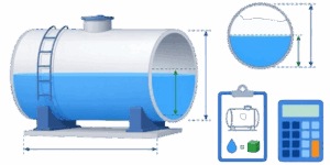
Accurate liquid storage management is a cornerstone of modern industrial operations, agricultural logistics, and residential utility tracking. Whether dealing with commercial fuel facilities, chemical processing plants, agricultural liquid fertilizer setups, or home rainwater collection systems, knowing the exact status of your inventory is non-negotiable.



✍ Miscalculating fluid levels causes costly operational disruptions, hazardous material overflows, supply chain bottlenecks, or severe structural damage to storage pads. This reference manual provides a clear breakdown of tank volume calculation methods, geometric profiles, material properties, and step-by-step instructions for utilizing online calibration tools to track fluid assets with high accuracy.
Table of Contents
The Operational Value of Precise Tank Monitoring
Storage tanks are rarely just passive containers. They represent active capital and critical safety variables within any infrastructure. Regular volume tracking and precise level monitoring serve multiple core operational goals. Inventory reconciliation relies heavily on accurate calculations to verify that delivered quantities match purchase orders and to detect hidden system leaks. Custody transfer scenarios require reliable volumetric data to facilitate fair commercial transactions between suppliers and buyers.
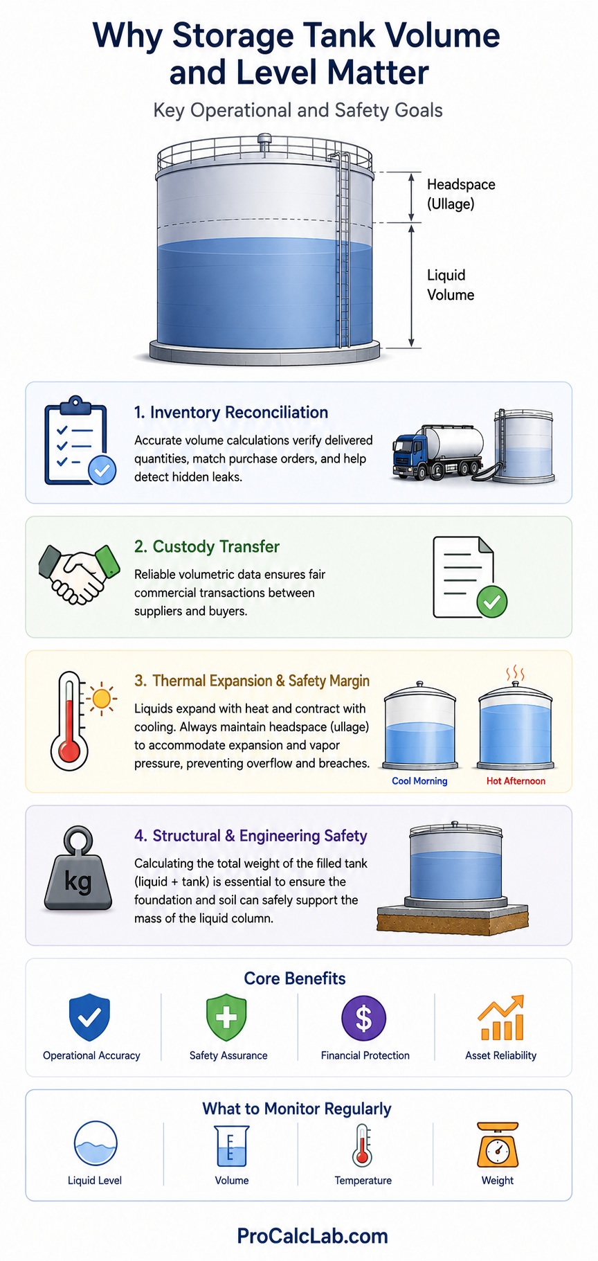
Safety margins represent another vital consideration. Liquids expand and contract with shifting environmental temperatures, causing changes in density while the total mass remains constant. For example, a fuel tank filled to absolute capacity during a cool morning can overflow during the heat of the afternoon as the liquid expands. Operators must always maintain a safety buffer, often called headspace or ullage, to accommodate vapor pressure and thermal expansion without risking a breach. Furthermore, calculating the total weight of a filled storage asset is vital for structural engineering safety, ensuring the supporting foundation or soil does not fail under the immense weight of the liquid column.
Understanding Tank Geometry: Shapes and Applications
Storage tank configurations are selected based on spatial limits, structural demands, and the physical behavior of the stored fluid. Different geometric shapes introduce unique calculation requirements. The two most common structural types found in residential and commercial settings are rectangular designs and cylindrical or conical variants.
Rectangular Configurations
Rectangular storage units, often referred to as box tanks, are widely used when space optimization is the primary design goal. These systems fit seamlessly into square basements, specialized shipping containers, or along the flat walls of warehouse facilities. They maximize the storage footprint by eliminating the dead spaces inherent to rounded structures. However, rectangular configurations are structurally less efficient at handling internal hydraulic pressure. The flat walls experience concentrated stress points along the vertical and horizontal corners, requiring thicker material shells or internal tie-rods to prevent the walls from bowing outward when fully loaded.
Cylindrical and Truncated Cone Profiles
Cylindrical designs distribute internal fluid pressure evenly across a continuous curved perimeter, allowing them to hold immense volumes with minimal material stress. When these tanks feature a tapered or truncated cone base, they provide exceptional utility for specific industrial processes. Tapered bottoms, frequently called hopper bases, use gravity to direct fluids, heavy sediments, or highly viscous materials toward a centralized bottom drain. This design ensures complete drainage during cleaning cycles and prevents the buildup of stagnant sludge at the base of the system, making them ideal for food processing, wastewater treatment, and chemical blending operations.
The Physics of Wall Thickness and Material Volume Displacement
🛢 A common error in manual tank calculations is failing to differentiate between the nominal external size of a tank and its actual internal storage capacity. The exterior measurements of a tank dictate its physical footprint within a building, but the thickness of the shell material reduces the space available for fluid containment.
For instance, a heavy industrial steel tank designed with half-inch thick plates will have a noticeably lower internal capacity than a flexible plastic tank with identical outer dimensions. Calculating inner dimensions requires subtracting the wall thickness from both sides of each horizontal axis, and subtracting it from the floor plate for vertical depth calculations. Ignoring this factor leads to systematic overestimation of inventory, resulting in purchasing errors and unexpected overflows.
A Complete Manual for the Online Storage Tank Volume Calculator
The online calculation tool simplifies these complex geometric formulas into a fast, user-friendly interface. It delivers accurate data regarding gross tank capacity, current liquid volume, empty headspace, material weight, and total structural weight. To achieve precision, users must gather raw data and input it into the designated fields according to the following guidelines.
Step 1: Select the System of Measurement
The user must first choose between the Imperial system and the Metric system. This selection updates all input labels and unit designations across the system. The Imperial setting utilizes inches for dimensions, pounds per cubic foot for material and liquid densities, and outputs volumes in gallons and cubic feet alongside total weights in pounds. The Metric setting utilizes millimeters for dimensions, kilograms per cubic meter for densities, and outputs volumes in liters and cubic meters alongside weights in kilograms.
Step 2: Choose the Geometric Profile
The operator selects the option that matches the physical layout of the tank. Choosing the rectangular profile activates fields for length, width, and height. Selecting the conical or cylindrical profile modifies the interface to collect the top diameter, bottom diameter, and total vertical height, which accommodates standard vertical cylinders, true cones, or tapered hopper designs.
Step 3: Input Physical Tank Dimensions
Carefully measure and input the physical boundaries of the storage system. For a rectangular tank, enter the maximum external length, external width, and total vertical height. For rounded or conical systems, enter the top internal or external diameter along with the bottom diameter. If the system is a standard vertical cylinder with no taper, the top and bottom diameter values must be identical. Input the total vertical height from the exterior base plate to the top edge of the sidewall.
Step 4: Define Wall Thickness and Current Fluid Level
Input the exact thickness of the shell material using the appropriate units. For steel systems, this value is often a fraction of an inch or several millimeters, while concrete or fiberglass systems will feature significantly larger wall profiles. Next, specify the filled percentage of the tank. This value represents the current liquid level relative to the total internal height. A value of zero indicates an entirely empty tank, while a value of one hundred represents a tank filled to its absolute internal limit.
Step 5: Establish Material and Liquid Densities
To calculate the physical mass of the empty structure and its liquid cargo, the tool requires accurate density inputs. The user inputs the density of the material used to construct the tank walls to determine the dry weight of the asset. Finally, enter the specific density of the stored liquid at its current operating temperature. Water features a standard benchmark density, but industrial chemicals, oils, or liquid sugars vary drastically, which heavily impacts the final structural load calculations.
The Core Mathematics: Formulas and Principles
The calculator processes the user inputs using standardized geometric and physical formulas. Understanding these equations helps operators interpret the data and perform manual checks when verifying field calculations.
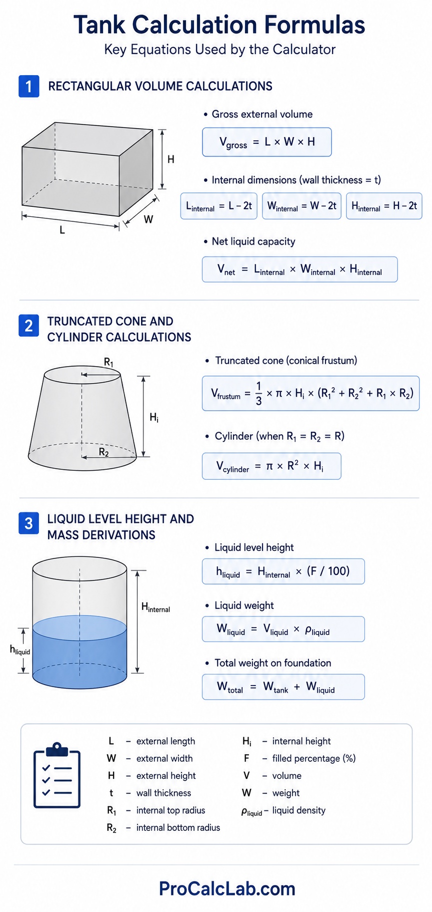
Rectangular Volume Calculations
To calculate the gross external volume of a rectangular tank, the system multiplies the external linear dimensions:
Vgross = L × W × H
To find the true fluid capacity, the tool calculates internal dimensions by adjusting for wall thickness, where the variable t represents the shell thickness:
Linternal = L – 2t
Winternal = W – 2t
Hinternal = H – 2t
The maximum net liquid capacity is then derived from these internal metrics:
Vnet = Linternal × Winternal × Hinternal
Truncated Cone and Cylinder Calculations
For cylindrical and tapered structures, the system relies on the conical frustum volume formula. The calculation utilizes the internal top radius, represented here as R1, and the internal bottom radius, represented as R2, along with the internal height, Hi:
Vfrustum = (1/3) × π × Hi × (R12 + R22 + R1×R2)
If the top and bottom radii are identical, this equation simplifies perfectly into the standard formula for a uniform vertical cylinder:
Vcylinder = π × R2 × Hi
Liquid Level Height and Mass Derivations
The actual depth of the liquid cargo from the bottom floor of the tank is determined directly by the user-supplied filled percentage, F:
hliquid = Hinternal × (F / 100)
Once the fluid volume is established, the physical weight of the liquid payload is derived by multiplying the calculated fluid volume by the liquid density value, ρliquid:
Wliquid = Vliquid × ρliquid
The total structural weight resting on the foundation pad is the sum of the empty tank shell mass and the fluid payload mass:
Wtotal = Wtank + Wliquid
Industrial Material and Fluid Density Reference Data
The following long-form reference tables provide standard density values for common storage liquids and tank construction materials. These figures can be entered directly into the calculator to achieve highly accurate structural weight assessments.
Table 1: Volumetric Densities of Common Industrial and Commercial Liquids
| Liquid Type | Imperial Density, lb/ft³ | Metric Density, kg/m³ |
|---|---|---|
| Pure Water (39°F / 4°C) | 62.4 | 1000 |
| Sea Water (Standard Salinity) | 64.0 | 1025 |
| Gasoline (Standard Unleaded) | 46.2 | 740 |
| Automotive Diesel Fuel | 53.1 | 850 |
| Crude Oil (Medium Grade) | 54.9 | 880 |
| Kerosene Jet Fuel | 50.6 | 810 |
| Ethylene Glycol (Antifreeze) | 69.3 | 1110 |
| Commercial Motor Oil (10W40) | 55.4 | 888 |
| Vegetable Cooking Oil | 57.4 | 920 |
| Glycerin (Pure Chemical Grade) | 78.7 | 1260 |
| Concentrated Sulfuric Acid (98%) | 114.9 | 1840 |
| Muriatic Hydrochloric Acid (31%) | 71.8 | 1150 |
| Sodium Hydroxide Liquid (50%) | 95.5 | 1530 |
| Corn Syrup (High Fructose) | 87.4 | 1400 |
| Heavy Industrial Molasses | 89.9 | 1440 |
| Whole Milk (Commercial) | 64.3 | 1030 |
| Isopropyl Alcohol (99%) | 49.0 | 785 |
| Pure Natural Honey | 88.6 | 1420 |
Table 2: Physical Densities of Common Tank Fabrication Materials
| Fabrication Material | Imperial Density, lb/ft³ | Metric Density, kg/m³ |
|---|---|---|
| Standard Carbon Steel | 490.0 | 7850 |
| Stainless Steel (Grade 304) | 494.0 | 7910 |
| Stainless Steel (Grade 316) | 500.0 | 8010 |
| Structural Aluminum (6061-T6) | 168.0 | 2700 |
| High-Density Polyethylene (HDPE) | 59.9 | 960 |
| Polypropylene Commercial Plastic | 56.8 | 910 |
| Fiberglass Reinforced Plastic (FRP) | 112.4 | 1800 |
| Reinforced Structural Concrete | 150.0 | 2400 |
| Pure Commercial Copper | 559.0 | 8950 |
| Yellow Brass Alloy | 530.0 | 8490 |
| Titanium (Grade 5) | 276.0 | 4430 |
Real-World Practical Case Study: Imperial Unit Analysis
To demonstrate the utility and workflow of the calibration system, this section reviews a practical scenario involving a rectangular steel storage tank utilized at an agricultural blending station in the United States. The operator needs to find the internal capacity, the real fluid height, and the total operational load resting on the support foundation.
Gathered Field Parameters
- Tank Structural Geometry: Rectangular Box Profile
- External Tank Length: 120 inches
- External Tank Width: 60 inches
- External Tank Height: 72 inches
- Wall Material Thickness: 0.50 inches
- Current Fluid Fill Level: 70 percent
- Tank Shell Material: Carbon Steel (490 lb/ft³)
- Stored Liquid Asset: Liquid Fertilizer Solution (75 lb/ft³)
Step-by-Step Computational Workflow
First, the internal dimensions must be calculated to eliminate the physical space occupied by the half-inch thick steel walls. The thickness affects both sides of the horizontal measurements and the bottom plate of the vertical orientation.
Internal Length = 120 – 2 × 0.50 = 119 inches
Internal Width = 60 – 2 × 0.50 = 59 inches
Internal Height = 72 – 2 × 0.50 = 71 inches
Next, calculate the total internal net volume of the empty structure in cubic inches by multiplying these adjusted linear dimensions:
Net Internal Volume = 119 × 59 × 71 = 498491 cubic inches
Because industrial operators in the United States measure fluid volumes in gallons and spatial footprints in cubic feet, these cubic inches must be converted using standard conversion constants, where one cubic foot equals 1728 cubic inches, and one gallon equals 231 cubic inches.
Net Capacity in Cubic Feet = 498491 / 1728 = 288.5 cubic feet
Net Capacity in Gallons = 498491 / 231 = 2158 gallons
The tank is currently reported as 70 percent full. The real liquid height from the internal floor of the container is determined by evaluating the internal vertical clearance:
Actual Liquid Height = 71 inches × (70 / 100) = 49.7 inches
The actual volume of the stored liquid fertilizer is found by applying the fill percentage to the total net internal capacity:
Current Liquid Volume = 2158 gallons × (70 / 100) = 1511 gallons
Current Liquid Spatial Footprint = 288.5 cubic feet × (70 / 100) = 202.0 cubic feet
To finalize the safety evaluation for the concrete storage pad, the operator calculates the weights. Multiply the current liquid cubic volume by the density of the fertilizer solution:
Liquid Weight Load = 202.0 cubic feet × 75 lb/ft³ = 15150 pounds
Assuming the calculated dry weight of this heavy steel tank shell is approximately 2800 pounds, the final structural load applied to the foundation is the combined mass of the container and its cargo:
Total Structural Load = 2800 + 15150 = 17950 pounds
The online tool generates these critical data points automatically, providing plant engineers with immediate information required for safe daily operations.
Pro Tips for Mitigating Measurement Errors in the Field
While the online calculator delivers flawless mathematical outputs based on the data provided, the final results are only as good as the measurements entered by the user. Implementing these operational strategies minimizes errors and maximizes on-site safety.
Account for internal structural components. Large tanks often feature internal baffles, structural reinforcing beams, or heavy mixing impellers. These elements displace fluid, reducing the true storage capacity. If your tank contains massive internal machinery, reduce the final calculated volume slightly to account for this displaced space.
Monitor temperature fluctuations. Liquids like oil, fuel, and chemical solutions experience clear volumetric shifts depending on temperature. Always measure fluid levels at a consistent time of day or utilize temperature-correction charts to adjust density inputs before entering data into the calculator. This ensures seasonal temperature shifts do not cause unexpected inventory discrepancies.
Inspect for sediment accumulation. Tanks holding wastewater, crude oils, or agricultural slurries accumulate a dense layer of solid sediment at the bottom over time. This layer acts as a false floor, reducing the active liquid storage space and altering the accuracy of dipstick readouts. Regular tank cleaning and bottom-level soundings prevent sediment from skewing calibration metrics.
Literature
- American Petroleum Institute. Standard 2550: Method for Measurement and Calibration of Upright Cylindrical Tanks. API Publishing, Washington DC, 2018.
- American Society for Testing and Materials. ASTM D1220: Standard Practice for Calculation of Petroleum and Petroleum Products Cargo Volumes. ASTM International, West Conshohocken, PA, 2021.
- Hydraulic Institute Standards for Industrial Fluid Storage and Management. Eleventh Edition, Hydraulic Institute, Parsippany, NJ, 2019.
- National Institute of Standards and Technology. Handbook 44: Specifications, Tolerances, and Other Technical Requirements for Weighing and Measuring Devices. US Department of Commerce, Washington DC, 2023.

Markus Fletcher — Structural Design Specialist
Expert in structural integrity, 3D modeling, and applied mathematics. Markus focuses on creating precise tools for construction professionals and DIY engineers.