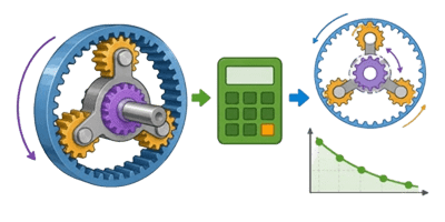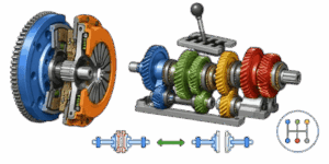
Understanding how engine power transfers to the wheels requires a solid grasp of friction, clamping forces, and rotational dynamics. The 3D Clutch and Gear Simulator provides a fully interactive visual model to help designers, mechanics, and automotive enthusiasts see exactly how these components interact in real-time. Rather than guessing whether a specific pressure plate and friction disc combination will hold the engine power, this tool calculates torque capacity and displays the mechanical engagement visually.
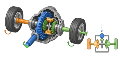
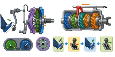

This guide explains how to operate the tool effectively and breaks down the mechanical principles behind drivetrain power transfer. The interface is divided into three distinct modes: Geometry, Mechanics, and Operation. Each mode controls specific variables that alter both the 3D model and the live mathematical output.
Table of Contents
How to Use the Simulator
Geometry Mode: Sizing the Components
The physical dimensions of a friction disc determine its overall surface area and its mechanical advantage. In Geometry mode, the sliders adjust the physical size of the components rendered on the screen.
Out Dia – Outer Diameter: This controls the overall width of the friction disc. A larger outer diameter increases the torque capacity because the friction material acts on a longer lever arm from the center axis. However, increasing this dimension also increases the rotational mass, which slows down engine responsiveness and makes gear shifts harder on the synchronizers.
In Dia – Inner Diameter: This slider defines the empty space in the center of the friction pad. Increasing the inner diameter reduces the total surface area. Less surface area means the clamping force is concentrated on a smaller region, which can increase wear and reduce the overall torque capacity. Finding the right balance between inner and outer diameters is critical for thermal management and longevity.
Mechanics Mode: Forces and Friction
Once the physical size is set, the mechanical properties of the materials and springs must be configured. These factors determine how much sheer power the system can handle before slipping occurs.
Clamp Force: This represents the total pressure exerted by the pressure plate springs against the friction disc and flywheel. High-performance vehicles require massive clamping forces to prevent slipping under heavy acceleration. Increasing this slider directly boosts the torque capacity, but in the real world, it also requires a much stiffer pedal feel for the driver.
Friction Mu: This is the coefficient of friction for the material on the disc. Organic materials used in standard street cars have a lower coefficient, allowing for smooth engagement. Racing materials like ceramic or sintered iron have a much higher coefficient, offering immense holding power but resulting in a harsh, aggressive engagement.
Operation Mode: Testing the System
The final mode simulates the drivetrain in motion, showing how engine speed and driver inputs affect the system state.
Engine RPM: This slider sets the rotational speed of the input shaft and flywheel. Higher RPM values mean more power is being transferred through the system, assuming the connection is fully locked. The 3D model will spin faster to reflect this input.
Pedal Percentage: This simulates the driver pressing the release pedal. At 0 percent, the system is fully engaged, and the pressure plate clamps the disc tightly against the flywheel. Between 10 and 60 percent, the system enters a slipping state, where the output shaft spins slower than the engine. Beyond 60 percent, the connection is fully severed, representing a disengaged state where no power transfers.
The Physics of Power Transfer
To understand the numbers generated in the results table, it helps to look at the math running behind the scenes. The calculations rely on standard mechanical engineering formulas adapted for disc friction. The tool uses a direct area-dependent formula to ensure that reducing the friction surface correctly lowers the holding capacity.
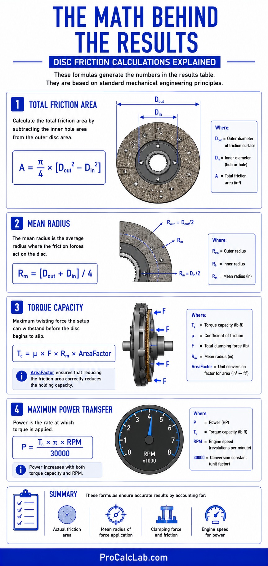
The total friction area is calculated using the outer and inner diameters. The formula subtracts the area of the inner hole from the total circular area.
A = π / 4 × [Dout2 – Din2]
The mean radius determines the average distance from the center where the friction forces are applied.
Rm = [Dout + Din] / 4
Torque capacity is the maximum twisting force the setup can withstand before the disc begins to slip against the flywheel. It depends on the clamping force, the friction coefficient, and the physical size of the contact patch. The formula incorporates an area factor to accurately scale the holding power.
Tc = μ × F × Rm × AreaFactor
Finally, the maximum power transfer is derived from the torque capacity and the current engine speed. Power is simply torque applied over time.
P = Tc × π × RPM / 30000
Reference Tables for Automotive Tuning
When setting up the simulator for a real-world build, using accurate baseline numbers is essential. The tables below combine metric and imperial units to accommodate different engineering standards. Measurements are presented with the metric value first, followed by the imperial equivalent separated by a slash.
Typical Friction Materials and Coefficients
Selecting the right friction material is a compromise between holding capacity and driving comfort. High-mu materials hold more power but engage abruptly.
| Material Type | Friction Mu | Primary Application |
|---|---|---|
| Organic Fiber | 0.25 – 0.35 | Standard Street / Daily Driving |
| Kevlar Blend | 0.35 – 0.45 | Heavy Duty Street / Towing |
| Carbon Semi-Metallic | 0.4 – 0.5 | Track Day / Autocross |
| Ceramic Puck | 0.5 – 0.6 | Drag Racing / Drifting |
| Sintered Iron | 0.6 – 0.7 | Dedicated Track / Pulling Trucks |
Standard Component Sizing
Disc diameters vary wildly depending on the vehicle class. Smaller discs rev faster, while larger discs handle massive torque spikes from heavy vehicles.
| Vehicle Class | Outer Diameter mm / in | Inner Diameter mm / in |
|---|---|---|
| Compact Car | 200 / 7.9 | 130 / 5.1 |
| Sports Coupe | 240 / 9.4 | 150 / 5.9 |
| Light Truck | 280 / 11 | 170 / 6.7 |
| Heavy Duty Diesel | 330 / 13 | 200 / 7.9 |
| Commercial Semi | 390 / 15.4 | 250 / 9.8 |
Clamp Force and Torque Ratings
The pressure plate springs dictate the clamping force. Upgrading the pressure plate is often required when adding forced induction to an engine.
| Plate Type | Clamp Force N / lbs | Max Torque Nm / lb-ft |
|---|---|---|
| OEM Standard | 4500 / 1000 | 270 / 200 |
| Stage 1 Upgrade | 6600 / 1500 | 400 / 300 |
| Stage 2 Heavy Duty | 8800 / 2000 | 540 / 400 |
| Stage 3 Extreme | 11100 / 2500 | 740 / 550 |
| Twin Disc Setup | 13300 / 3000 | 1200 / 885 |
Practical Example: Sizing a Racing Setup
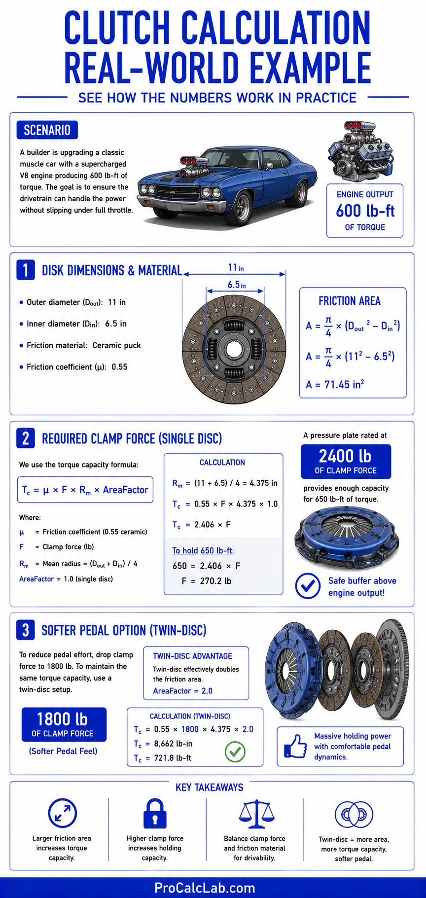
✍ Let us walk through a practical scenario to demonstrate how the calculations play out in the real world. A builder is upgrading a classic muscle car with a supercharged V8 engine. The engine produces 600 lb-ft of torque. The builder needs to ensure the drivetrain can handle this output without slipping under full throttle.
The builder selects a standard high-performance outer diameter of 11 inches. To maximize the friction area, they choose an inner diameter of 6.5 inches. Using an organic material would require a massive clamping force to hold 600 lb-ft, resulting in an undrivable pedal feel. Instead, the builder opts for a ceramic puck design with a friction coefficient of 0.55.
With the physical size and friction material locked in, the only remaining variable is the pressure plate clamp force. Using the principles demonstrated in the simulator, the builder determines that a pressure plate rated at 2400 lbs of clamping force will provide enough holding capacity for 650 lb-ft of torque. This provides a safe buffer above the engine maximum output, ensuring the connection remains solid during aggressive gear shifts.
If the builder wanted a softer pedal feel, they would need to drop the clamp force to 1800 lbs. To maintain the same torque capacity with less clamping force, they would have to switch to a twin-disc setup. A twin-disc system essentially doubles the friction area without increasing the overall diameter, allowing for massive holding power with comfortable pedal dynamics.
Troubleshooting Common Drivetrain Issues
The interactive model helps visualize how things should work ideally. However, in the real world, mechanical components fail or perform poorly due to incorrect setup. Here are common issues and the mechanical reasons behind them.
System Slipping Under Load
Slipping occurs when the engine RPM climbs rapidly, but the vehicle speed does not increase proportionally. This means the torque capacity has been exceeded. Looking at the formulas, this happens because the clamp force is too weak, the friction material has glazed over and lost its Mu value, or the friction area has been worn down to the rivets. Upgrading to a higher Mu material or a stiffer pressure plate resolves this.
Dragging and Hard Shifting
Dragging happens when the pedal is fully depressed, but the transmission still receives rotational energy. In the simulator, this is equivalent to the pedal slider being at 100 percent, but the output shaft continuing to spin. Mechanically, this means the pressure plate is not lifting far enough away from the friction pad. This is often caused by a failing hydraulic cylinder, stretched cables, or a warped flywheel. Because the connection is never fully severed, the transmission synchronizers fight against engine power, making it incredibly difficult to shift gears.
Shudder and Chatter on Engagement
Shudder is a violent vibration felt through the vehicle frame as the pedal is released. It happens during the slipping phase between 10 and 60 percent engagement. Ceramic and sintered iron materials are notorious for this because their high friction coefficient causes them to aggressively grab and release the flywheel rapidly rather than sliding smoothly. Flywheel hot spots – areas of hardened steel caused by extreme thermal cycles – also create uneven friction surfaces that lead to chatter.
Advanced Concepts: Upgrading and Tuning
For high-performance applications, simple single-disc setups often reach their physical limits. Upgrading requires changing the architecture of the system entirely.
Puck Style Friction Pads
Standard street vehicles use a full-face disc, meaning the friction material forms a complete continuous circle. Racing applications often use puck-style pads, which look like a star with four or six separate pads. While this actually reduces total surface area, it drastically increases the pressure applied per square inch. This concentrated pressure allows high-mu materials to bite aggressively into the flywheel. Furthermore, the empty spaces between the pucks allow extreme heat and friction dust to escape, preventing the material from glazing over during intense track sessions.
Twin and Triple Disc Systems
When engine output exceeds 800 lb-ft of torque, a single disc simply cannot hold the power without an impossibly stiff pressure plate. Multi-disc systems solve this by stacking two or three friction pads separated by steel floater plates. This effectively multiplies the total friction area. A twin-disc system can hold twice the torque of a single-disc system using the exact same clamping force, resulting in a pedal feel that is similar to a stock commuter car but capable of handling drag-racing launches.
Lightweight Flywheels
The flywheel acts as a kinetic energy battery. A heavy steel flywheel stores a lot of energy, making it easy to drive in stop-and-go traffic because the engine resists stalling. However, a heavy flywheel takes longer to accelerate. Swapping to a lightweight aluminum flywheel removes rotational mass from the input group. The engine revs much faster, providing better throttle response. The tradeoff is that the driver must apply more throttle when pulling away from a stop, as there is less stored inertia to get the heavy chassis moving.
Summary
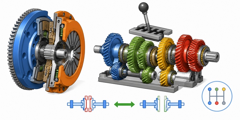
The 3D simulator bridges the gap between abstract math and physical reality. By manipulating the outer and inner diameters, clamping forces, and material friction coefficients, users can see exactly how design choices impact mechanical limits. Whether sizing components for a weekend autocross build or diagnosing a slipping drivetrain on a heavy-duty tow rig, understanding the relationship between surface area, pressure, and leverage is the key to reliable power transfer.
Further Reading and Reference Material
- Automotive Engineering Fundamentals – Rotational Dynamics and Drivetrain Systems
- Society of Automotive Engineers Standards for Transmission Interfaces
- High-Performance Friction Materials and Thermal Capacity Limits
- Mechanical Design of Machine Elements – Clamp Load and Surface Pressure Distribution

David Parry — Senior Engineering Analyst
Specializing in electronics and physics-based simulations with 20+ years of engineering experience. David ensures the mathematical and physical accuracy of the tools at ProCalcLab.