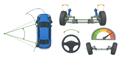
Every wheeled vehicle with an engine needs a reliable way to transfer power to the ground while allowing the drive wheels to spin at completely different speeds. This mechanical magic happens inside the differential. When a vehicle takes a corner, the outside wheel travels a significantly longer path than the inside wheel. Without a differential mechanism, the tires would scrub against the pavement, hop, and bind. This causes massive drivetrain stress, unpredictable handling, and rapid tire wear.


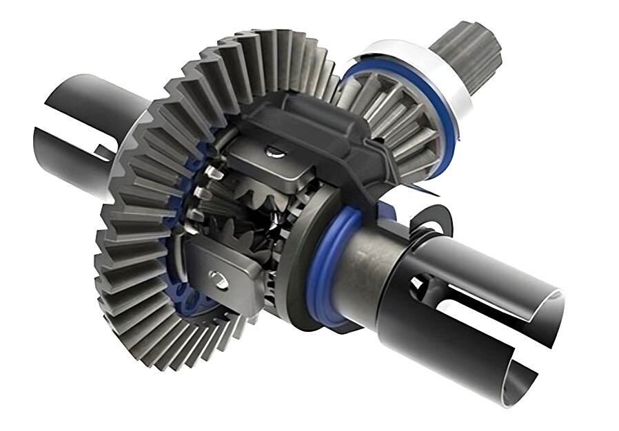
The 3D Differential Simulator brings this complex mechanical interaction to life. The tool allows users to visualize exactly how spider gears and axle gears interact under various driving conditions right in the browser.
Table of Contents
Complete User Guide for the 3D Simulator
This visual calculator is designed for mechanics, engineering students, and automotive enthusiasts who want to see the math behind the metal. The interface is broken down into simple sliders and mode selectors. Users do not need a degree in mechanical engineering to get results. The tool renders a live 3D model that updates instantly as values change.
Adjusting the Geometrical Parameters
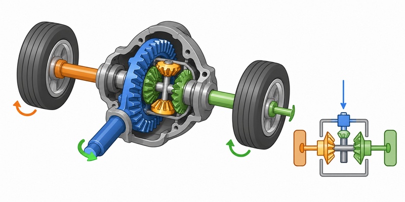
Axle Gears: This slider changes the number of teeth on the side gears. These are the gears splined directly to the left and right axle shafts. Increasing the tooth count makes the gears larger in diameter. This visibly alters the mesh angle inside the carrier.
Spider Gears: This controls the number of teeth on the smaller pinion gears that ride on the cross-pin. These gears walk around the side gears when the vehicle turns. Changing their size alters the overall gear ratio between the carrier and the axles during a slip condition.
Spider Count: Standard light-duty differentials use two spider gears. Heavy-duty trucks and performance vehicles use four spider gears to distribute torque loads more evenly. Toggling this slider adds or removes gears from the 3D carrier cross-pin.
Setting the Motion Variables
Carrier RPM: This represents the input speed from the driveshaft after passing through the ring and pinion gears. It sets the baseline speed for the entire housing. Setting this to 60 RPM provides a clear, easy-to-follow visual pace for the animation.
Turn Bias: This slider only appears in the Turn mode. It dictates the speed percentage difference between the left and right wheels. A higher bias simulates a much sharper turn where the inside wheel slows down drastically and the outside wheel speeds up proportionately.
Operating the Kinematic Modes
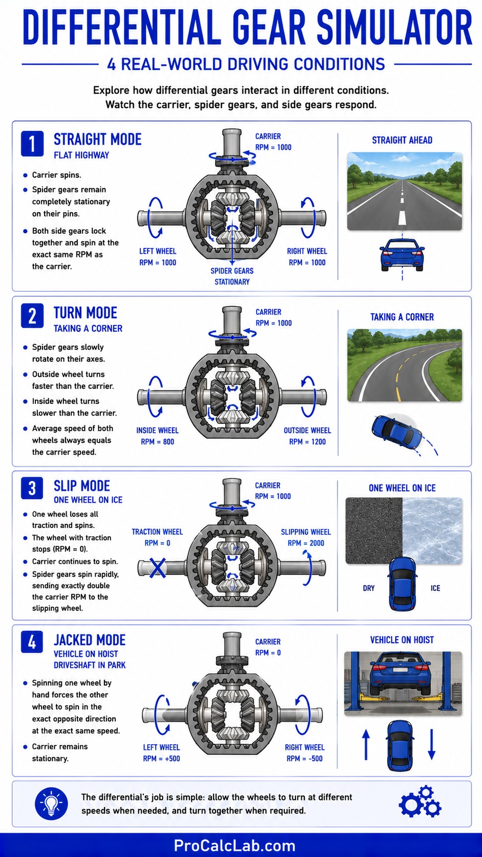
The simulator features four distinct real-world driving conditions to test the gear interactions.
- Straight Mode: Simulates driving down a flat highway. The carrier spins, but the spider gears remain completely stationary on their pins. Both side gears lock together and spin at the exact same RPM as the carrier.
- Turn Mode: Simulates taking a corner. The spider gears begin to slowly rotate on their axes. This allows the outside wheel to turn faster than the carrier while the inside wheel turns slower. The average speed of both wheels always equals the carrier speed.
- Slip Mode: Simulates one wheel hitting a patch of pure ice while the other remains on dry pavement. The wheel with traction stops entirely. The carrier continues to spin. The spider gears spin rapidly, sending exactly double the carrier RPM to the slipping wheel.
- Jacked Mode: Simulates the vehicle lifted on a mechanic hoist with the driveshaft locked in park. Spinning one wheel by hand forces the other wheel to spin in the exact opposite direction at the exact same speed. The carrier remains stationary.
Core Differential Physics and Formulas
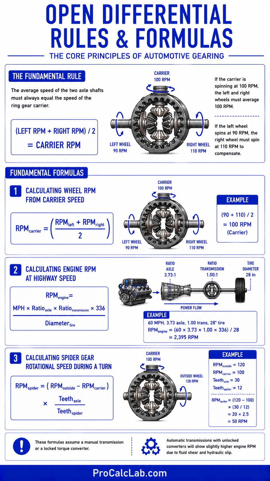
🎓 The fundamental rule of a standard open differential is simple. The average speed of the two axle shafts must always equal the speed of the ring gear carrier. If the carrier is spinning at 100 RPM, the left and right wheels must average 100 RPM. If the left wheel spins at 90 RPM, the right wheel must spin at 110 RPM to compensate.
Here are the fundamental formulas used in automotive gearing analysis. They are written plainly for easy reference.
Calculating Wheel RPM from Carrier Speed:
RPMcarrier = (RPMleft + RPMright) / 2
Calculating Engine RPM at Highway Speed:
RPMengine = (MPH × Ratioaxle × Ratiotransmission × 336) / Diametertire
Calculating Spider Gear Rotational Speed during a turn:
RPMspider = (RPMoutside – RPMcarrier) × (Teethaxle / Teethspider)
These formulas assume a manual transmission or a locked torque converter. Automatic transmissions with unlocked converters will show slightly higher engine RPM due to fluid shear and hydraulic slip.
Practical Example: Setting Up a Classic Muscle Car
🚗 Let us look at a real-world garage scenario using Imperial measurements. A builder is setting up a classic rear-wheel-drive muscle car for highway cruising and light drag racing. The car runs a 28-inch tall rear tire. The driver wants to cruise at 65 MPH down the interstate without the engine screaming past 3000 RPM. The transmission has a 1:1 final drive ratio in high gear.
The builder is considering a 3.73 rear axle ratio. We use the standard RPM formula to check the cruising speed.
RPM = (65 × 3.73 × 1 × 336) / 28
RPM = 81463.2 / 28
RPM = 2909
The result is 2909 RPM at 65 MPH. This is a very acceptable cruising speed for a traditional V8 engine. If the builder chose a more aggressive 4.11 gear ratio for harder acceleration off the starting line, the highway RPM would jump to 3205 RPM. That difference makes the car much louder and thirstier on long road trips. The 3.73 ratio is the perfect middle ground for this specific tire size.
Comprehensive Gear Ratio and Tire Size Reference Tables
Matching tire size to the correct differential gear ratio is critical for maintaining vehicle performance, fuel economy, and transmission health. Running large tires with factory gears puts massive strain on the transmission and makes the vehicle feel sluggish. Below are extensive reference tables for both Imperial and Metric systems to help builders choose the right setup.
Table 1: Imperial Engine RPM at 65 MPH
This table shows the calculated engine RPM at 65 miles per hour assuming a 1:1 final transmission drive. Green zone indicates good fuel economy. Yellow indicates a performance or towing bias. Red indicates extreme setups not recommended for daily highway driving.
| Tire Diameter, In | 3.08 Ratio | 3.55 Ratio | 3.73 Ratio | 4.10 Ratio | 4.56 Ratio | 4.88 Ratio | 5.13 Ratio |
|---|---|---|---|---|---|---|---|
| 27 | 2490 | 2870 | 3015 | 3315 | 3686 | 3945 | 4147 |
| 28 | 2401 | 2768 | 3000 | 3196 | 3555 | 3804 | 3999 |
| 29 | 2318 | 2672 | 2808 | 3086 | 3432 | 3673 | 3861 |
| 30 | 2241 | 2583 | 2714 | 2983 | 3318 | 3551 | 3733 |
| 31 | 2169 | 2500 | 2627 | 2887 | 3211 | 3436 | 3612 |
| 32 | 2101 | 2422 | 2545 | 2797 | 3110 | 3329 | 3499 |
| 33 | 2037 | 2348 | 2468 | 2712 | 3016 | 3228 | 3393 |
| 35 | 1921 | 2214 | 2326 | 2557 | 2844 | 3043 | 3199 |
| 37 | 1817 | 2094 | 2201 | 2419 | 2690 | 2879 | 3026 |
| 40 | 1681 | 1937 | 2036 | 2237 | 2488 | 2663 | 2799 |
Table 2: Metric Engine RPM at 105 KM/H
For international builders using metric tire dimensions. The formulas shift slightly to accommodate millimeters and kilometers per hour. This assumes a 1:1 transmission final drive.
| Tire Diameter, mm | 3.08 Ratio | 3.55 Ratio | 3.73 Ratio | 4.10 Ratio | 4.56 Ratio | 4.88 Ratio | 5.13 Ratio |
|---|---|---|---|---|---|---|---|
| 680 | 2520 | 2904 | 3051 | 3354 | 3730 | 3992 | 4197 |
| 710 | 2413 | 2781 | 2922 | 3212 | 3573 | 3823 | 4019 |
| 740 | 2315 | 2668 | 2804 | 3082 | 3428 | 3668 | 3856 |
| 770 | 2225 | 2564 | 2694 | 2962 | 3294 | 3525 | 3706 |
| 800 | 2142 | 2468 | 2593 | 2851 | 3171 | 3393 | 3567 |
| 840 | 2040 | 2351 | 2470 | 2715 | 3020 | 3232 | 3397 |
| 890 | 1925 | 2219 | 2331 | 2562 | 2850 | 3050 | 3206 |
| 940 | 1823 | 2101 | 2207 | 2426 | 2698 | 2888 | 3036 |
| 1000 | 1713 | 1975 | 2075 | 2281 | 2536 | 2714 | 2854 |
Differential Types and Their Practical Applications
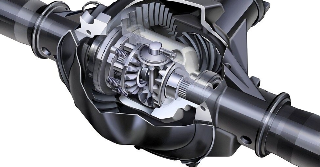
The standard open differential shown by default in the simulator is just the baseline. Automotive manufacturers have developed several variations to overcome the biggest weakness of the open design. That weakness is the tendency to send all engine power to the wheel with the least traction.
The Open Differential
This is the most common design found in passenger cars and light SUVs. It uses the exact spider and axle gear setup visualized in the 3D tool. It provides smooth, quiet cornering and predictable handling on dry pavement. However, if one wheel drops into slippery mud, the spider gears spin wildly, sending 100 % of the rotational speed to the slipping wheel while the wheel on solid ground does absolutely nothing.
The Limited Slip Differential
Also known as an LSD. This design adds clutch packs or complex helical gears behind the axle gears. When one wheel begins to slip, the internal friction of the clutches or gears binds the two axle shafts together partially. This sends vital torque to the wheel that still has traction. Muscle cars and sports cars rely heavily on LSD units to launch off the starting line without spinning just one tire into smoke.
The Locking Differential
Lockers are strictly for off-road vehicles, heavy trucks, and dedicated drag cars. A mechanical lock completely binds the left and right axle shafts together. The spider gears are entirely bypassed or locked solid. In this state, both wheels spin at the exact same speed regardless of traction or turning angles. Driving a locked differential on dry pavement causes loud tire chirping and massive stress on the axle shafts during corners.
The Spool
A spool replaces the entire differential carrier with a solid chunk of machined steel. There are no spider gears and no moving parts inside. The ring gear bolts to the spool, and the axle shafts slide straight in. It is physically impossible for the wheels to turn at different speeds. Spools are strictly for dedicated track cars and mud boggers. They are dangerously unpredictable and illegal for street use.
Diagnosing Differential Wear and Failure Symptoms
Because the differential sits far away from the driver and operates completely out of sight, it is usually ignored until something breaks. Mechanics rely on specific auditory and physical symptoms to diagnose differential health. Knowing what these sounds mean can save thousands of dollars in catastrophic failure repairs.
- Whining on Acceleration: A high-pitched howl or whine that only happens when pressing the gas pedal usually points to worn pinion bearings or an improper ring and pinion mesh depth. The gears are grinding together at the wrong angle under load.
- Whining on Deceleration: If the whine appears only when lifting off the throttle and coasting, the pinion bearing preload has likely loosened. The pinion gear is physically pulling away from the ring gear and riding on the extreme edges of the gear teeth.
- Rumble at Speeds Over 20 MPH: A low-pitched rumble that vibrates the entire floorboard indicates worn carrier bearings. The heavy steel carrier is physically wobbling inside the cast iron housing.
- Clunking When Shifting into Drive: A loud metallic clack when shifting an automatic transmission from Park to Drive indicates excessive backlash. The gap between the ring gear teeth and pinion gear teeth has grown too wide. The driveshaft spins freely for a fraction of a second before slamming into the ring gear.
- Chattering Around Tight Corners: If the rear tires chirp or the rear end shudders during slow, tight turns in a parking lot, the limited-slip clutch packs are binding. The differential fluid is likely degraded, or the friction modifier additive has completely worn out.
Essential Maintenance and Fluid Specs
Heavy steel gears sliding against each other under massive torque loads generate extreme heat. Differential gear oil is specifically engineered to withstand sheer forces that would instantly destroy standard motor oil. Most light-duty trucks and cars require fluid changes every 30000 to 50000 miles. Vehicles used for heavy towing or water crossings require much more frequent service.
Table 3: Common Fluid Viscosity Applications
| Vehicle Application | Recommended Fluid Viscosity | Typical Capacity, Pints |
|---|---|---|
| Standard Passenger Cars | 75W-90 Synthetic | 2.5 to 3.5 |
| Light Duty Trucks | 75W-90 or 80W-90 Conventional | 4.0 to 5.5 |
| Heavy Duty Towing | 75W-140 Synthetic | 6.0 to 8.0 |
| High Performance Track Cars | 75W-110 Synthetic with Friction Modifier | 3.0 to 4.5 |
| Dedicated Off-Road Crawlers | 85W-140 Conventional | 5.0 to 7.0 |
Always consult the specific factory service manual for exact capacities. Overfilling a differential causes the heavy gear oil to foam up. Foamed oil provides zero lubrication and builds enough pressure to blow out the rubber axle seals, ruining the rear brakes.
Understanding Axle Spline Counts and Strength
🛠 The axle shaft connects the differential side gears directly to the wheels. The end of the axle shaft is machined with long grooves called splines. These splines slot directly into the center of the side gears. The number of splines directly dictates the total strength and torque capacity of the axle shaft.
A 28-spline axle is standard for light cars. A 31-spline or 33-spline axle is thicker and significantly stronger, making it common in heavy trucks and high-horsepower drag cars. Upgrading to higher spline counts requires completely replacing the differential carrier and side gears to match the new axle diameter. You cannot fit a 31-spline axle into a 28-spline side gear.
Conclusion
The interactive 3D Simulator provides a flawless visual representation of rules that mechanics have relied on for over a century. By adjusting the spider gear counts, varying the carrier RPM, and toggling between slip and turn modes, the intricate dance of differential kinematics becomes completely transparent. Use the reference tables to ensure accurate real-world builds, and always respect the heavy torque loads these components endure daily.
Reference Material and Bibliography
- Automotive Drivetrain and Manual Transmissions. CDX Automotive. Fundamentals of gear reduction and torque multiplication.
- High-Performance Differentials, Axles, and Drivelines. Joe Palazzolo. Detailed breakdown of limited-slip clutch pack rebuilding and ring gear setups.
- Differentials: Identification, Restoration and Repair. Jim Allen and Randy Lyman. Industry standard specifications for backlash, pinion depth, and carrier preload mapping.
- Standard Catalog of American Light-Duty Trucks. John Gunnell. Factory axle codes and gear ratio documentation for classic restorations.
- Machinerys Handbook. Industrial Press. Geometrical formulas for bevel gear tooth generation and mechanical tolerances.

David Parry — Senior Engineering Analyst
Specializing in electronics and physics-based simulations with 20+ years of engineering experience. David ensures the mathematical and physical accuracy of the tools at ProCalcLab.