
| Parameter | Recommendation |
|---|
This tool speeds up relay selection and gives practical sizing for contact ratings, peak current capability, contact layout, protection measures and a life estimate. It uses inputs such as system voltage, steady and inrush currents, load class, switching frequency and operating environment to produce actionable recommendations for relay selection.


Table of Contents
Who benefits from this relay selection aid
- Auto electricians and mechanics who need a quick, reliable starting point for choosing relays and protection.
- Hardware designers and OEM engineers who must specify contact ratings and service life.
- Hobbyists and installers fitting pumps, fans, heaters and aftermarket electronics to vehicles.
Inputs required for accurate relay selection
- System voltage, typically 12 or 24 volts, specify actual working voltage.
- Steady current of the load under normal operation.
- Inrush or peak current at turn on for motors or filament lamps.
- Load type, choose resistive, inductive, capacitive, DC motor or LED drive. Load type changes contact area and arc suppression needs.
- Switching activity, number of cycles per hour. High duty favors solid state switching.
- Operating conditions such as temperature, humidity and vibration that reduce contact life.
- Preferred relay family, electromechanical, solid state or hybrid.
- Required life in cycles or years at expected switching rate.
Outputs you will get
- Recommended relay family: electromechanical, solid state or hybrid.
- Coil or control voltage options and interface requirements for SSR drive.
- Contact current rating rounded to a standard value with a safety margin.
- Suggested peak or pulse rating to withstand inrush currents.
- Contact configuration advice such as SPST, SPDT or DPDT for reversing circuits.
- Protection recommendations including fuse type, TVS, RC snubber or freewheel diode.
- Estimated electrical life in cycles and a years estimate at the given switching rate.
- Suggested safety margin expressed as a multiplier of steady current.
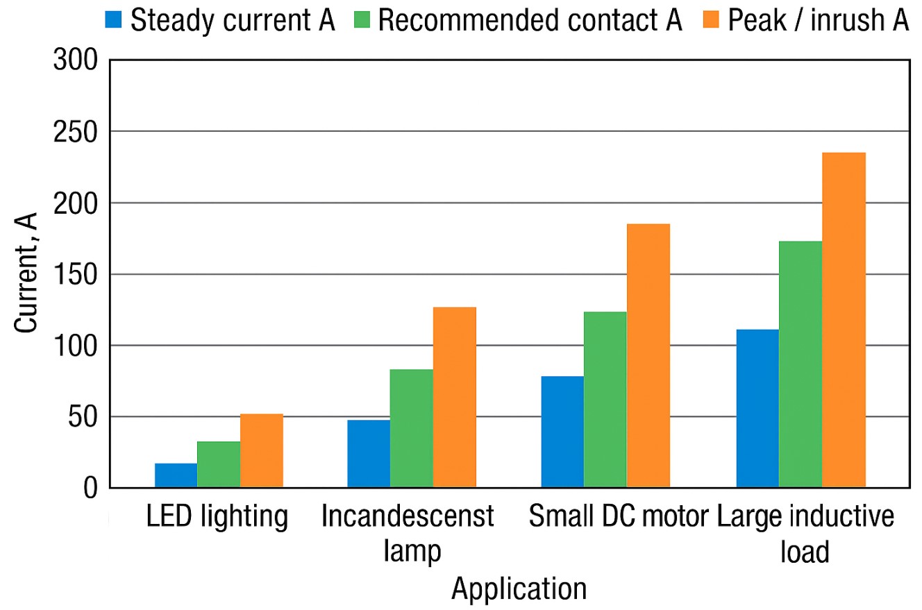
Selection principle and quick formulas
Follow these steps for sizing contacts and protection when performing relay selection.
- Take steady current I nom and peak current I pk. Pick contact rating equal or above I nom times a safety factor k specific to load type. Typical k values are: resistive 1.25, LED or electronics 1.5, capacitive 1.8, inductive 2.2, DC motor 2.5.
- Ensure peak rating covers I pk. If I pk greatly exceeds contact rating, add soft start or choose higher rating.
- For switching rates above one hundred cycles per hour prefer SSR or hybrid devices for long life.
- Fit arc suppression for inductive circuits and current limiting for lamp and motor starts.
- Choose fuse to protect wiring using a multiplier of 1.25 to 1.5 times steady current while considering inrush.
Practical sizing example
- System voltage 24 V
- Steady current 52 A
- Inrush peak 310 A
- Switching 30 cycles per hour
- Required life 250000 cycles
Compute safety factor for motor type 2.5, recommended contact algorithm gives
✍ I rec = maximum of rounded standard and I nom plus half of I pk. For these numbers recommended contact rating is near 200 A and fuse about 100 A with soft start advised.
Additional technical guidance
- Derating with temperature. Contacts and SSRs must be derated at elevated ambient temperature. Consult datasheet curves and reduce continuous current accordingly.
- Contact material. Silver alloy contacts resist welding and provide low contact resistance. For corrosive environments use plated or sealed relays.
- DC versus AC. DC breaking is more severe. Double the attention on arc energy and choose relays with specific DC ratings.
- Solid state devices. SSRs have no contacts and provide long cycle life but require thermal management. Estimate power dissipation from on resistance and provide heatsinking.
- Leakage and off-state. SSRs and MOSFET switches can leak small currents when off. Check if this is acceptable for the load.
- Snubber and TVS sizing. Typical RC snubber starts at 0.01 microfarads and 100 ohms. Choose TVS to clamp slightly above system voltage for transient suppression.
- Fuse selection. Use slow blow fuses for motor or lamp inrush. Use fast blow fuses for pure electronics protection.
- Mechanical and mounting. In vibration environments choose relays rated for shock and vibration. Secure connectors and use locking harnesses.
- EMC and switching noise. Soft starting and snubbers reduce electromagnetic interference. Place suppression close to the switching device.
- Testing. Validate candidate relay on the actual load, measure contact temperature, check welding after repeated cycles.
Reference table: recommended relay types and protections
| Application | Preferred relay type | Contact rating guideline | Protection |
|---|---|---|---|
| LED lighting and small electronics | SSR or MOSFET switch | 10 to 40 A depending on load | TVS and fuse |
| Incandescent lamps and heaters | Electromechanical relay | 15 to 35 A taking inrush into account | NTC inrush limiter and fuse |
| Small DC motors and pumps | Electromechanical or hybrid | 40 to 250 A depending on power | Freewheel diode, TVS, soft start and fuse |
| Large inductive loads | EMR with arc suppression or hybrid | 50 to 300 A | RC snubber, TVS and fuse |
| High frequency switching | SSR or MOSFET | Rating depends on thermal dissipation | Heatsink and thermal interlock |
Common questions on relay selection
Can SSRs be used for motors? They work well for moderate loads but check inrush and heat dissipation. For large starting currents prefer EMR or hybrid solutions.
How to choose a fuse? Select fuse rated 1.25 to 1.5 times steady current, choose slow blow for loads with predictable inrush. Confirm selective coordination with downstream devices.
Which matters more, peak or steady rating? Both matter. Steady rating governs continuous heating and life. Peak rating protects against short term surges. Address large peaks with soft start or higher contact rating.
Decision checklist for relay selection
- Record actual voltage and steady current.
- Measure or estimate inrush and duty cycle.
- Decide on relay family based on switching frequency and load type.
- Apply temperature derating and pick a contact rating from standard series.
- Specify arc suppression and correct fuse type.
- Prototype and test under real conditions.
Relay selection balances contact rating, surge handling and service life. Use calculated safety margins, apply derating for temperature, and provision protection. Validate final choice on the actual load and consult datasheets for precise limits.

Further reading
- The Art of Electronics, Paul Horowitz and Winfield Hill
- Power Electronics, Converters, Applications and Design, Ned Mohan
- Automotive Electrics, Electronics and Engine Management, Tom Denton

David Parry — Senior Engineering Analyst
Specializing in electronics and physics-based simulations with 20+ years of engineering experience. David ensures the mathematical and physical accuracy of the tools at ProCalcLab.