| Parameter | Value |
|---|---|
| Load Voltage | — V |
| Voltage Drop | — V |
| Voltage Drop percent. | — % |
| Power Loss | — W |
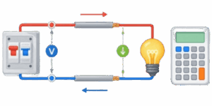
Moving electricity from one location to another always involves some energy loss. Every wire acts like a small resistor. When electrical current flows through a metal wire, the internal resistance of that metal converts some of the electrical energy into heat. As a result, the voltage measured at the exact end of the wire is lower than the voltage measured at the starting power source. Engineers refer to this exact physical reduction as voltage drop.


⚡ This calculator provides a fast and accurate way to determine exactly how much voltage disappears along any wire run. Planning electrical projects requires ensuring that connected equipment receives enough power to operate safely. When voltage drops too low, electrical motors struggle to spin properly. This mechanical struggle causes the motors to draw significantly more current, which creates excess heat. Eventually, this trapped heat destroys the internal motor windings. Lights running on low voltage will dim noticeably or flicker continuously. Electronic devices like computers or televisions will shut down or restart unpredictably. Electrical building codes strictly regulate exactly how much energy a circuit is legally allowed to lose.
Table of Contents
How to Use the Calculator
The interface requires 0 advanced technical knowledge to operate. Users only need basic details about their planned electrical project. Follow these exact steps to get accurate results.
Step 1: Choose the Unit System
The top section provides 2 buttons for unit selection. Selecting the Imperial button changes all distance measurements to feet and all diameter measurements to inches. Selecting the Metric button switches all values to meters and millimeters. Choose the system that matches your physical tape measure and wire specifications.
Step 2: Select the Phase Type
The tool handles 2 distinct types of electrical networks. Select 1-Phase for standard residential outlets, battery systems, solar setups, or automotive wiring. Direct current acts identically to 1-Phase alternating current for resistive heat calculations because the power travels out on 1 wire and returns on 1 wire. Select 3-Phase only for heavy commercial or industrial equipment that utilizes 3 active power wires simultaneously.
Step 3: Select the Conductor Material
The drop-down list contains 6 distinct material options. Copper stands as the absolute gold standard for general building conductivity. Aluminum costs less and weighs less but requires noticeably thicker gauges to carry the exact same current safely. Steel offers high physical tensile strength for long overhead spans but has terrible electrical conductivity. Silver conducts electricity slightly better than Copper but costs far too much for standard wiring. Gold resists natural corrosion perfectly and serves well in tiny electronic microchips but fails as a bulk wire material due to extreme price. Brass provides physical durability for physical terminals but ranks incredibly low in raw conductivity.
Step 4: Adjust the Slider Inputs
The interface features 5 main input categories. Users can move the sliders or type exact digits into the text boxes.
- Voltage: Enter the starting voltage at the main breaker panel or battery. Common values include 12, 24, 120, 240, or 480 Volts.
- Distance: Enter the total physical length of the wire run from the source directly to the load. Do not double this distance for the return wire path. The internal calculator code handles the return path math automatically.
- Diameter and Area: These 2 fields link together automatically. Adjusting the physical diameter automatically updates the mathematical cross-sectional area. If the exact wire gauge is known, refer to the reference tables below to find the correct area to input.
- Power: Enter the exact load requirement in kilowatts. For a standard 1500 Watt heater, type 1.5 into the box.
Step 5: Read the Results
The dynamic results table updates instantly. The Load Voltage row displays the exact voltage remaining for the actual device to use. The Voltage Drop row shows exactly how many Volts vanished as heat along the wire path. The Voltage Drop Percentage row shows the lost voltage calculated as a percentage of the original starting voltage. Finally, the Power Loss row displays the exact wasted energy measured in Watts.

Mathematical Formulas
The calculator utilizes basic Ohm Law principles combined with geometric volume mathematics to generate results. The basic fundamental relationship between voltage, current, and resistance uses the following simple formulas:
Basic Voltage Drop Equation:
$$V_{drop} = I \cdot R$$
Basic Power Loss Equation:
$$P_{loss} = V_{drop} \cdot I$$
To calculate the specific resistance of a physical wire, the system must account for the material resistivity, the total wire length, and the wire area. The calculation for 1-Phase applications requires accounting for the round trip of the current moving out and back. The complex math looks like this:
$$V_{drop}=\frac{2\cdot\rho\cdot{L}\cdot{I}}{A}$$
For 3-Phase electrical systems, the offset timing of the alternating current changes the mathematical multiplier from 2 to the exact square root of 3:
$$V_{drop}=\frac{\sqrt{3}\cdot\rho\cdot{L}\cdot{I}}{A}$$
Practical Example Walkthrough
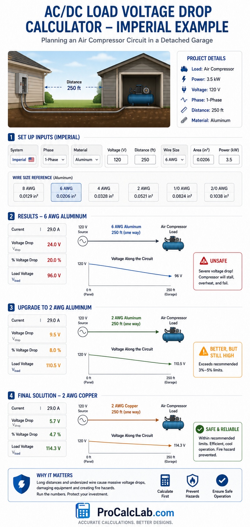
The following example illustrates how to plan a project using Imperial numbers. A property owner wants to install a heavy air compressor inside 1 detached garage. The physical distance from the main house electrical panel to the exact garage location measures exactly 250 feet. The compressor motor requires exactly 3.5 kilowatts of power to start and run properly. The circuit operates on a standard 120 Volts 1-Phase power supply. The selected wire material is Aluminum to save on bulk installation costs.
First, the user clicks the Imperial system button. Next, the user selects the 1-Phase option. Then, the user opens the material drop-down list and clicks Aluminum. Moving to the inputs, the user sets the Voltage to 120 and the Distance to 250. The user decides to test 6 AWG wire. Checking the reference table below, 6 AWG has an exact area of 0.0206 square inches. The user types 0.0206 into the Area field. Finally, the user types 3.5 into the Power field.
The visual canvas and results table update immediately. The tool shows the compressor draws over 29 Amps of current. Pushing 29 Amps through 500 total feet of 6 AWG Aluminum wire creates massive electrical resistance. The results table reveals a devastating voltage drop of roughly 24 Volts. This equals a 20 % loss. The actual load voltage reaching the garage drops to a mere 96 Volts.
At 96 Volts, the air compressor motor will stall, overheat, and suffer permanent internal damage. To fix this dangerous issue, the user must increase the wire size. Changing the physical wire from 6 AWG to 2 AWG changes the area input to 0.0521 square inches. The calculation instantly updates, dropping the loss to 9.5 Volts. This equals an 8 percent loss. The load voltage rises to 110 Volts. However, this still exceeds standard 3 % or 5 % safety recommendations.
The user decides to change the material selection from Aluminum back to Copper while keeping the large 2 AWG size. Copper conducts energy much more efficiently. The calculation updates a final time. The voltage drop falls to a completely safe 5.7 Volts. This equals a 4.7 % loss. The final load voltage reaches 114 Volts. This result sits perfectly within acceptable limits for a dedicated long-distance motor circuit. The user successfully prevented a catastrophic fire hazard simply by running the numbers first.
Engineering Reference Tables
American Wire Gauge Specifications
Use this table to find the exact Imperial area for the input fields.
| AWG Size | Diameter in Inches | Area in Square Inches |
|---|---|---|
| 4/0 | 0.4600 | 0.1662 |
| 3/0 | 0.4096 | 0.1318 |
| 2/0 | 0.3648 | 0.1045 |
| 1/0 | 0.3249 | 0.0829 |
| 1 | 0.2893 | 0.0657 |
| 2 | 0.2576 | 0.0521 |
| 3 | 0.2294 | 0.0413 |
| 4 | 0.2043 | 0.0328 |
| 5 | 0.1819 | 0.0260 |
| 6 | 0.1620 | 0.0206 |
| 7 | 0.1443 | 0.0163 |
| 8 | 0.1285 | 0.0130 |
| 9 | 0.1144 | 0.0103 |
| 10 | 0.1019 | 0.0081 |
| 11 | 0.0907 | 0.0065 |
| 12 | 0.0808 | 0.0051 |
| 13 | 0.0720 | 0.0041 |
| 14 | 0.0641 | 0.0032 |
| 15 | 0.0571 | 0.0026 |
| 16 | 0.0508 | 0.0020 |
| 17 | 0.0453 | 0.0016 |
| 18 | 0.0403 | 0.0013 |
| 19 | 0.0359 | 0.0010 |
| 20 | 0.0320 | 0.0008 |
| 21 | 0.0285 | 0.0006 |
| 22 | 0.0253 | 0.0005 |
| 24 | 0.0201 | 0.0003 |
| 26 | 0.0159 | 0.0002 |
| 28 | 0.0126 | 0.0001 |
Material Resistivity Properties
The base mathematical constants used internally by the calculator algorithm.
| Material Name | Metric Constant | Conductivity Rank |
|---|---|---|
| Silver | 0.0160 | 1 |
| Copper | 0.0175 | 2 |
| Gold | 0.0240 | 3 |
| Aluminum | 0.0280 | 4 |
| Brass | 0.0700 | 5 |
| Steel | 0.1300 | 6 |
Standard Safety Limits
Always verify local laws before installing permanent electrical infrastructure.
| Circuit Type | Max Allowed Percentage Loss |
|---|---|
| Lighting Branch Circuits | 3 |
| Sensitive Electronics | 3 |
| Heating Branch Circuits | 3 |
| Motor Dedicated Circuits | 5 |
| Main Feeder Lines | 2 |
| Solar Panel DC Runs | 2 |
| Automotive Audio Lines | 5 |
| Total System Limit | 5 |
Reference Bibliography
- National Fire Protection Association, National Electrical Code, 2023 Edition.
- Institute of Electrical and Electronics Engineers, Standard Handbook for Electrical Engineers, 17th Edition.
- American Society for Testing and Materials, Standard Specification for Concentric-Lay-Stranded Copper Conductors, 2021 Revision.
- International Electrotechnical Commission, International Standard 60228, Conductors of Insulated Cables.
- Underwriters Laboratories, Standard 83 for Thermoplastic-Insulated Wires and Cables.

David Parry — Senior Engineering Analyst
Specializing in electronics and physics-based simulations with 20+ years of engineering experience. David ensures the mathematical and physical accuracy of the tools at ProCalcLab.


