
Understanding the internal dimensions of cylindrical objects is a fundamental skill for fabricators, engineers, and construction professionals across the United States. Whether working on massive concrete pillars, steel water tanks, or routing wires through industrial conduits, knowing the exact internal clearances prevents costly errors. This comprehensive guide explains the geometry behind cylindrical sections, demonstrates how to perform the calculations using imperial units, and shows exactly how our interactive tool streamlines your daily workflow.


Table of Contents
Understanding the Geometry of Cylinders
A standard straight cylinder consists of 3 basic surfaces: 2 flat circular bases and 1 continuous curved side. When professionals talk about the footprint of a cylinder, they are usually referring to the diameter. The diameter is the straight line passing directly through the center of the circular base, touching the edges on both sides. We denote this value with the letter D. The radius, denoted as R, is exactly 1/2 of the diameter.
✍ The height of the cylinder, represented by the letter H, is the vertical distance running straight from the bottom base to the top base. In a perfect right cylinder, this line is exactly perpendicular to the ground.
What is a Vertical Cross Section?
Imagine taking a large industrial pipe and slicing it perfectly down the middle from top to bottom. If you open that pipe and look directly at the flat cut surface, you will see a rectangle. This flat rectangular plane is known as the vertical cross section or axial section.
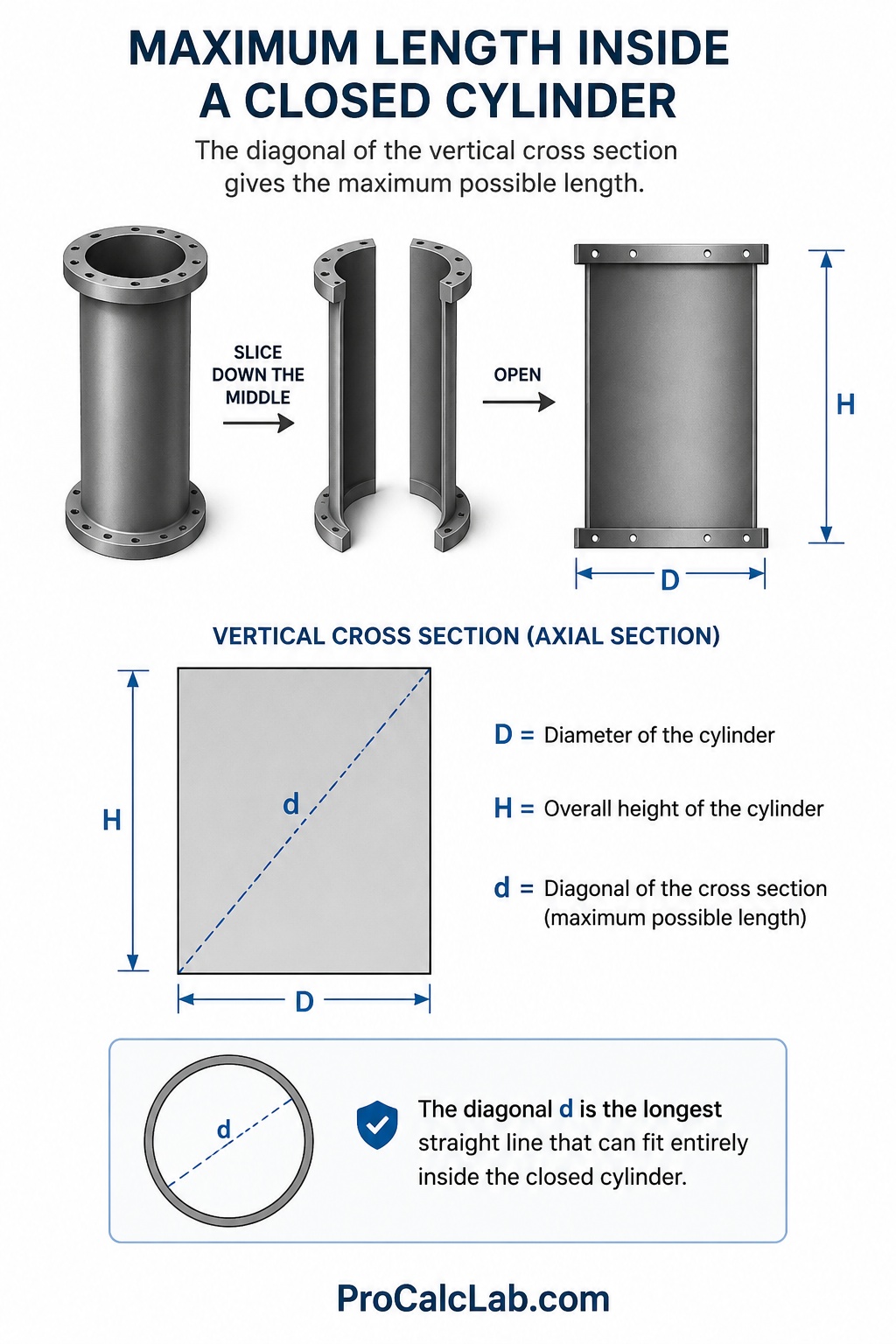
This internal rectangle has 2 main dimensions. The width of this rectangle is exactly equal to the diameter D of the cylinder. The height of this rectangle is exactly equal to the overall height H of the cylinder. The diagonal of this cross section is the longest straight line you can draw inside that rectangle, running from the bottom left corner all the way to the top right corner. We represent this line with the small letter d. Knowing the exact length of d tells you the absolute maximum length of any rigid, non-bending object that can fit entirely inside the closed cylinder.
The Mathematics Behind the Diagonal
Because the vertical section is a perfect rectangle, the diagonal line cuts it into 2 identical right triangles. This means we can rely on classic geometry to find our answers. The math relies heavily on the Pythagorean theorem.
To find the length of the diagonal, use this standard formula:
d = √[ D2 + H2 ]
This means you square the diameter, square the height, add those 2 numbers together, and finally extract the square root of the sum. Our online tool handles this heavy lifting instantly.
Another crucial metric is the cross-sectional area. This tells you the total flat square footage of that internal slice. The formula for the area S is simply:
S = D * H
Finally, we often need to know the tilt angle of that diagonal line relative to the flat bottom base. We use the symbol α for this angle. The formula uses inverse trigonometry:
α = arctan[ H / D ]
How to Use the Interactive Diagonal Calculator
We designed the visual calculator on this page to completely eliminate manual math errors. It provides instant visual feedback and highly accurate numbers for your blueprints or fabrication shop floor.
- Step 1: Enter your radius or diameter. You can use the slider for a quick visual estimation, or type the exact number into the input box for precision. If you know the diameter is 24 inches, simply enter 12 into the radius box.
- Step 2: Enter the overall height of your object. Again, move the slider or type the exact number.
- Step 3: Watch the 3D model update instantly. The interactive graphic on the screen will reshape itself to match your exact proportions. The red diagonal line and the yellow internal plane show you exactly what is being measured.
- Step 4: Review the results table. The program instantly calculates the full diameter, the total cross-sectional area, the exact angle of the tilt, and the crucial diagonal length.
- Step 5: Export your data. Once your numbers are dialed in, hit the download button. The program will generate a high-quality image containing the 3D visual, the flat blueprint view, and the complete data table. You can attach this file directly to your client emails or print it for the shop floor.
Crucial Measurement Tips for Fabricators
The numbers generated by the tool are mathematically perfect. However, the real world is rarely perfect. When applying these dimensions to physical steel, wood, or plastic, you must account for real-world tolerances.
📏 Always measure the internal diameter rather than the outside diameter. A heavy-duty steel pipe might have an outside diameter of 12 inches but wall thickness of 1 inch on each side. That means your actual usable internal diameter D is only 10 inches. Entering 12 instead of 10 will give you a diagonal that is entirely useless for fitting internal components.
Leave a clearance gap. If your math says the internal diagonal is exactly 120 inches, do not build an insert that is 120 inches long. Metal expands with heat, and concrete forms bulge under pressure. Always subtract 1 % or 2 % from your final rigid component length to ensure a smooth installation.
Practical Application: A Real-World Workshop Example
Let us walk through a practical scenario using imperial units. A custom fabrication shop is building a specialized stainless steel mixing vat for a chemical plant. The blueprints dictate that the internal diameter D must be exactly 8 feet. The internal straight side height H must be exactly 15 feet. The engineering team needs to install a solid, unbendable titanium sensor rod diagonally across the inside of the empty vat. They need to know the maximum length of this rod and the total flat area of the center dividing baffle. Input values: D = 8, H = 15.
First, we determine the cross-sectional area for the flat baffle plate.
S = D * H
S = 8 * 15 = 120
The shop needs to order a steel plate covering exactly 120 square feet.
Next, we calculate the maximum length for the titanium sensor rod.
d = √[ 82 + 152 ]
Square the numbers:
8 * 8 = 64
15 * 15 = 225
Add them together:
64 + 225 = 289
Extract the square root:
d = √289 = 17
The absolute maximum length of the titanium rod is exactly 17 feet. If they order an 18 foot rod, it will not fit inside the closed vat.
Finally, we check the installation angle.
α = arctan[ 15 / 8 ]
15 / 8 = 1.875
α = 61.93 degrees.
The welding team must set their jigs to approximately 62 degrees to properly mount the rod.
Industry Use Cases: Where This Math Matters
This geometry is not just for classroom tests. It is the backbone of several major American industries.
Logistics and Shipping
Air freight often utilizes cylindrical cargo pods to perfectly match the curved fuselage of aircraft. Loadmasters must calculate if long rigid crates can be angled inside these pods. If a cargo pod has an internal diameter of 6 feet and a length of 10 feet, the diagonal limits what can be shipped. Any rigid pipe or lumber bundle longer than the calculated diagonal simply must be shipped via a different method.
Commercial Construction
Modern architecture relies heavily on poured concrete pillars. Frequently, heavy steel rebar cages or internal drainage pipes must be routed inside the concrete forms before pouring. Foremen use the axial section dimensions to ensure the rebar grids do not scrape against the cardboard forming tubes. Knowing the diagonal guarantees the internal framework remains perfectly centered.
Lumber and Sawmilling
A raw tree log is essentially a rough cylinder. When a log hits the sawmill, the sawyer must visualize the largest possible rectangular beam that can be cut from the center. The cross section of the log dictates the maximum width and depth of the premium heartwood timber. An inaccurate estimation results in excessive waste and lost profit.
Reference Tables for Common Dimensions
To speed up your daily planning, we have compiled extensive reference tables. These cover standard sizes found across American job sites. All decimal numbers are rounded to a maximum of 2 decimal places.
Table 1: Diagonal Lengths for Standard Industrial Pipes
This table lists internal measurements for typical heavy duty scheduling pipes, calculated in inches.
| Internal Diameter D, in | Pipe Length H, in | Diagonal d, in |
|---|---|---|
| 4 | 24 | 24.33 |
| 4 | 48 | 48.17 |
| 6 | 36 | 36.50 |
| 6 | 72 | 72.25 |
| 8 | 48 | 48.66 |
| 8 | 96 | 96.33 |
| 10 | 60 | 60.83 |
| 10 | 120 | 120.42 |
| 12 | 72 | 72.99 |
| 12 | 144 | 144.50 |
| 18 | 90 | 91.78 |
| 24 | 120 | 122.38 |
| 30 | 150 | 152.97 |
| 36 | 180 | 183.56 |
| 48 | 240 | 244.75 |
Table 2: Container Proportions and Tilt Angles
The ratio between height and diameter drastically changes the geometry. This table shows how the shape dictates the internal angle.
| Ratio H / D | Tilt Angle α, degrees | Visual Shape Description |
|---|---|---|
| 0.1 | 5.71 | Extremely flat disc |
| 0.2 | 11.31 | Hockey puck shape |
| 0.5 | 26.57 | Shallow wading pool |
| 0.8 | 38.66 | Standard tire shape |
| 1.0 | 45.00 | Perfectly square profile |
| 1.2 | 50.19 | Typical soup can |
| 1.5 | 56.31 | Standard 55 gallon drum |
| 2.0 | 63.43 | Tall water heater |
| 3.0 | 71.57 | Street lamp post |
| 4.0 | 75.96 | Structural piling |
| 5.0 | 78.69 | Flagpole |
| 8.0 | 82.87 | Long drill bit |
| 10.0 | 84.29 | Thin wire segment |
| 15.0 | 86.19 | Extended cable |
| 20.0 | 87.14 | Optical fiber |
Table 3: Cross-Sectional Areas for Architectural Columns
Architects need the plane area for wind load calculations and facing material estimates. Measurements are in feet.
| Diameter D, ft | Height H, ft | Area S, sq ft |
|---|---|---|
| 1 | 8 | 8 |
| 1 | 10 | 10 |
| 1.5 | 9 | 13.5 |
| 1.5 | 12 | 18 |
| 2 | 10 | 20 |
| 2 | 16 | 32 |
| 2.5 | 14 | 35 |
| 3 | 15 | 45 |
| 3 | 20 | 60 |
| 4 | 25 | 100 |
| 5 | 30 | 150 |
| 6 | 40 | 240 |
| 8 | 50 | 400 |
| 10 | 80 | 800 |
| 12 | 100 | 1200 |
Manual mathematics on a busy job site often lead to transposed digits or missed decimal points. A single calculation error regarding a custom steel insert can result in thousands of dollars in wasted materials and days of lost labor. By utilizing precise digital tools, you lock in accuracy before a single piece of material is cut. Always run your dimensions through the digital interface, confirm the 3D visual matches your intent, and export the blueprint for your records.
Literature
If you want to master the deeper principles of structural geometry and industrial mathematics, we highly recommend adding these standard American reference books to your professional library.
- Oberg E. — Machinery’s Handbook. The absolute gold standard for mechanical engineers and machinists in the United States.
- Giesecke F. — Technical Drawing with Engineering Graphics. A masterful guide on how to properly draft and read complex 3D blueprints.
- Kibbe R. — Machine Tool Practices. Excellent practical breakdown of shop floor mathematics and precision measurements.
- Brown & Sharpe — Practical Treatise on Milling and Milling Machines. Contains phenomenal insights into cutting cylindrical profiles.
- Alexander D. — Essential Math for Construction. A straightforward, no-nonsense guide specifically tailored for builders and contractors.

Markus Fletcher — Structural Design Specialist
Expert in structural integrity, 3D modeling, and applied mathematics. Markus focuses on creating precise tools for construction professionals and DIY engineers.


