| Parameter | Formula | Result |
|---|
Precision geometry forms the absolute core of structural integrity. A layout error of merely 0.5° at the origin point magnifies into a massive 10 inch deviation over a 100 ft distance. Professional builders demand mathematical perfection before cutting expensive materials or pouring concrete. The Diagonal Angle Calculator removes manual trigonometry from the workflow, delivering instant visual and numerical data. Knowing the exact intersection angle and length of internal lines guarantees a flawless build. Whether snapping chalk lines for a 40 ft warehouse slab or fabricating a custom 15 inch steel bracket, verifying the cross-measurements remains the only fail-proof method for ensuring true squareness and symmetry.


Relying solely on edge measurements invites catastrophic failure. Materials warp, saw blades deflect, and tape measures stretch. When 4 sides of a frame measure exactly exactly to plan, the internal angles can still skew, creating a parallelogram instead of a perfect rectangle. Checking the cross-span distance instantly reveals these hidden deformities. If the 2 diagonal lines match perfectly down to the 0.01 inch mark, the internal corners are locked at exactly 90°. This principle applies across all trades — from heavy timber framing to delicate custom cabinetry.
Table of Contents
Operating the Calculator Interface on the Job Site
The software interface prioritizes speed for field workers wearing gloves or viewing screens in bright sunlight. 3 main navigation tabs sit at the top: Rectangle, Rhombus, and Trapezoid. Tapping 1 of these tabs alters the mathematical engine and the visual canvas. Below the tabs, an interactive drawing board displays the current geometric profile. The control section below the canvas features heavy-duty sliders and manual numeric input fields. Moving a slider instantly morphs the shape on the screen, allowing users to visualize extreme proportions. Typing specific data like 144.5 into the input box locks exact project dimensions into the algorithm.
📝 The results table updates instantly with every input adjustment. This grid displays the raw diagonal lengths, the exact arithmetic formulas used for the calculation, and the final intersection angles. The math output relies strictly on pure geometric theorems. The user interface includes 2 critical utility buttons. The Reset button clears all custom data, returning the fields to standard default parameters. The Download button captures a high-resolution snapshot of the entire schematic and data table. This image saves directly to local device storage, allowing a site foreman to text the exact layout specs to a framing crew across the job site.
Rectangular Geometry in Heavy Framing and Foundations
Rectangles dominate the built environment. Plywood sheets, concrete footings, and structural steel frames rely on 90° corners. The math governing these shapes remains incredibly straightforward. The diagonal line cutting across the internal space acts as the hypotenuse of a right triangle. Finding this length requires applying the Pythagorean theorem. The formula translates to: d = √[a2 + b2]. The angle where the 2 cross-lines meet depends entirely on the ratio between the short side and the long side. A perfect square creates exactly 90° intersections. A long, narrow hallway creates a very tight acute angle and a very wide obtuse angle.
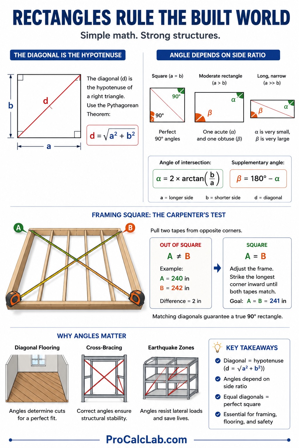
When framing a floor deck, carpenters pull 2 steel tapes simultaneously from opposite corners. If tape A reads 240 inches and tape B reads 242 inches, the deck is out of square. The crew must strike the longest corner with a sledgehammer, driving the frame inward until both tapes read exactly 241 inches. Calculating the angle of intersection α requires the formula: α = 2 * arctan[b / a]. The supplementary angle β is found via: β = 180 – α. Knowing these angles proves critical when laying hardwood flooring on a bias or installing diagonal cross-bracing in earthquake zones.
| Profile Dimensions a * b [ft] | Exact Diagonal Length d [ft] | Acute Intersection Angle α [°] |
|---|---|---|
| 4 * 8 | 8.94 | 53.13 |
| 6 * 8 | 10.00 | 73.74 |
| 8 * 10 | 12.81 | 77.32 |
| 8 * 12 | 14.42 | 67.38 |
| 10 * 12 | 15.62 | 79.61 |
| 12 * 16 | 20.00 | 73.74 |
| 16 * 20 | 25.61 | 77.32 |
| 20 * 24 | 31.24 | 79.61 |
| 24 * 30 | 38.42 | 77.32 |
| 30 * 40 | 50.00 | 73.74 |
| 40 * 60 | 72.11 | 67.38 |
| 50 * 100 | 111.80 | 53.13 |
| 60 * 120 | 134.16 | 53.13 |
| 100 * 200 | 223.61 | 53.13 |
Rhombus Geometry for Custom Fabrication and Tile Work
A rhombus features 4 outer boundaries of identical length, but the internal corners deviate from 90°. This shape appears frequently in custom architectural details, including diamond-shaped windows, specialized roof trusses, and intricate floor medallions. The defining geometric trait of a rhombus dictates that its 2 diagonals will always intersect at exactly 90°, regardless of the outer proportions. The intersecting point also cuts each span into 2 perfectly equal halves. This creates 4 identical right triangles inside the perimeter, simplifying area calculations and material estimating.
Calculating the lengths requires knowledge of the exterior side length a and 1 of the internal corner angles γ. The formula for the 1st diagonal is: d1 = 2 * a * sin[γ / 2]. The formula for the 2nd diagonal is: d2 = 2 * a * cos[γ / 2]. When a tile setter plans a diamond pattern across a 500 sq ft lobby, getting these calculations wrong leads to massive material waste. The grid must align perfectly with the main entrance. Knowing the exact cross-measurements allows the installer to snap precise chalk lines across the subfloor, creating an infallible guide for the adhesive application.
| Corner Angle γ [°] | Length Multiplier for d1 | Length Multiplier for d2 |
|---|---|---|
| 30 | 0.52 | 1.93 |
| 40 | 0.68 | 1.88 |
| 45 | 0.77 | 1.85 |
| 50 | 0.85 | 1.81 |
| 60 | 1.00 | 1.73 |
| 70 | 1.15 | 1.64 |
| 80 | 1.29 | 1.53 |
| 90 | 1.41 | 1.41 |
| 100 | 1.53 | 1.29 |
| 110 | 1.64 | 1.15 |
| 120 | 1.73 | 1.00 |
| 135 | 1.85 | 0.77 |
| 150 | 1.93 | 0.52 |
Trapezoid Layouts for Complex Roofing and Angled Lots
Trapezoidal shapes present the highest level of difficulty during field layouts. A standard trapezoid possesses only 2 parallel lines — the top base and the bottom base. The side lines connect at various pitches. This geometry dominates modern roofing systems, specifically hip roofs and dormers. Land surveyors also encounter this shape constantly, as very few urban property lines form true rectangles. In an asymmetrical profile, the 2 diagonals feature entirely different lengths, and their crossing point sits off-center.
To accurately map this shape, 4 variables must be established: base a, base b, the perpendicular height h, and the horizontal offset x. The formula for the 1st diagonal is: d1 = √[h2 + [x + b]2]. The formula for the 2nd diagonal is: d2 = √[h2 + [x – a]2]. If framing a cathedral ceiling with exposed beams, the angle of intersection between cross-ties must be exact for the metal gusset plates to fit. The manual vector math required to find this angle takes excessive time, making the digital calculator an essential tool for maintaining job site momentum.
| Construction Task | Max Diagonal Deviation [in] | Max Angular Defect [°] |
|---|---|---|
| Rough Timber Framing | 0.50 | 0.50 |
| Concrete Slab Forms | 0.25 | 0.25 |
| Steel Beam Fabrication | 0.12 | 0.10 |
| Exterior Brick Veneer | 0.12 | 0.10 |
| Hardwood Floor Install | 0.06 | 0.05 |
| Custom Kitchen Cabinetry | 0.03 | 0.02 |
| Glass Window Glazing | 0.01 | 0.01 |
| CNC Machine Routing | 0.005 | 0.001 |
Field Scenario 1: Framing a Standard Deck
A residential building crew prepares to frame a large outdoor deck. The architectural plans specify a footprint measuring 12 ft by 16 ft. Before sinking the support posts into the concrete footings, the perimeter string lines must be verified for absolute squareness. Using the rectangular logic, the variables are a = 12 and b = 16. The hypotenuse formula applies directly.
d = √[122 + 162]
d = √[144 + 256]
d = √[400]
d = 20
The cross-measurement must read exactly 20 ft. If 1 string reads 20.2 ft and the other reads 19.8 ft, the layout is severely skewed. The crew adjusts the corner batter boards until both strings land dead on 20 ft. The intersection angle α is calculated as 2 * arctan[16 / 12] = 2 * 53.13 = 106.26°. This angle dictates the cut for any diagonal deck boards running through the center of the frame.
Field Scenario 2: Building a Custom Diamond Window
A finish carpenter receives a work order to build a wooden frame for a custom diamond-shaped window. The design is a perfect rhombus. The outer frame pieces each measure 24 inches. The bottom corner must sit at a tight 60° angle. To cut the interior glass correctly, the glazier needs the exact vertical and horizontal cross-span dimensions. The variables are a = 24 and γ = 60.
d1 = 2 * 24 * sin[60 / 2]
d1 = 48 * sin[30]
d1 = 48 * 0.5
d1 = 24
d2 = 2 * 24 * cos[60 / 2]
d2 = 48 * cos[30]
d2 = 48 * 0.866
d2 = 41.57
The glass must be cut exactly 24 inches wide and 41.57 inches tall. Because this is a rhombus, the installer knows these 2 lines will cross perfectly at 90°, allowing for standard cross-hair laser alignment during the final installation sequence into the wall cavity.
Field Scenario 3: Pouring an Angled Concrete Driveway
A concrete contractor must pour a driveway expansion that abuts a non-parallel property line. The shape forms an asymmetrical trapezoid. The bottom base against the garage measures 10 ft. The top base at the street measures 6 ft. The straight perpendicular height is 8 ft. The property line creates a 0 ft offset on 1 side. The variables are a = 10, b = 6, h = 8, and x = 0. To ensure the form boards are staked correctly before the cement trucks arrive, the contractor computes the 2 distinct cross-spans.
d1 = √[82 + [0 + 6]2]
d1 = √[64 + 36]
d1 = √[100]
d1 = 10
d2 = √[82 + [0 – 10]2]
d2 = √[64 + 100]
d2 = √[164]
d2 = 12.8
The form boards are locked into place only when tape measure 1 reads exactly 10 ft and tape measure 2 reads exactly 12.8 ft. This mathematical lock prevents the driveway from encroaching onto the neighbor’s property line while maintaining the required square abutment against the existing garage slab.
Mitigating Environmental Errors During Measurement
Mathematical perfection on a screen frequently clashes with physical reality on a job site. The most common cause of geometric failure involves tape measure sag. When measuring a 50 ft span suspended in the air, gravity pulls the heavy steel ribbon downward. This belly creates a false reading. A measurement that appears to be 50.1 ft on a sagging tape might actually be exactly 50 ft when pulled dead straight. Professionals counteract this by applying a strict 10 lbs of tension for every 100 ft of unsupported tape.
🌡 Thermal expansion presents an equally dangerous threat to layout accuracy. Standard measuring tools are calibrated at 68°F. The expansion coefficient for carbon steel is roughly 0.00000645 per 1°F. If a crew performs a layout on a blistering 105°F afternoon, the steel expands significantly. A 100 ft span measured under these conditions contains an unseen error of 100 * 0.00000645 * 37 = 0.0238 ft, which equals nearly 0.3 inches. On a massive commercial foundation, failing to mathematically compensate for this thermal distortion guarantees that the prefabricated steel columns will not align with the embedded anchor bolts.
Laser distance meters eliminate tape sag entirely, but they introduce their own set of challenges. Bright sunlight washes out the laser dot, making it impossible to hit the exact target corner at distances exceeding 30 ft. Furthermore, a laser beam must hit a perfectly vertical target plate. If the target plate tilts backward by just 2°, the hypotenuse calculation stretches, corrupting the data. The most resilient method involves combining digital calculations, laser verification, and physical string lines pulled at extreme tension to form a redundant validation matrix.
Literature
- Modern Carpentry — Willis H. Wagner
- Mathematics for Carpentry and the Construction Trades — Alfred Webster
- Precision Framing — Mike Guertin
- The Very Efficient Carpenter — Larry Haun
- Roofing Construction and Estimating — Daniel Atcheson
- Site Layout Leveling and Surveying — Harvey V. Brand

Markus Fletcher — Structural Design Specialist
Expert in structural integrity, 3D modeling, and applied mathematics. Markus focuses on creating precise tools for construction professionals and DIY engineers.


