| Dimensions: | 0.00×0.00×0.00 |
| Slice Area: | 0.00 in² |
| Surface Area: | 0.00 in² |
| Part Volume: | 0.00 in³ |
| Final Weight: | 0.00 oz |
Accurate material estimation forms the backbone of successful manufacturing. Whether preparing a file for a desktop 3D printer or ordering raw stock for a multi-axis CNC mill, knowing the exact physical properties of a digital model is an absolute requirement. Guessing material usage leads to interrupted production cycles, wasted resources, and ruined parts. This guide breaks down exactly how to evaluate digital geometries, extract vital metrics like volume and surface area, and translate those numbers into real-world weight and cost forecasts.


Table of Contents
Core Functions of the Digital Evaluation Tool
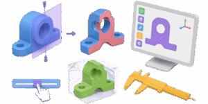
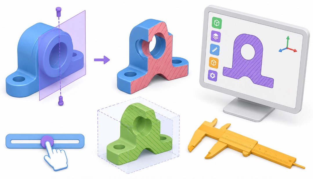
The interactive 3D evaluation interface simplifies the transition from a digital mesh to a physical object. The system reads the raw geometry data from standard engineering formats like STL, OBJ, and GLTF. It then processes the triangular faces to calculate exact mathematical properties. Here is a breakdown of what the platform provides and why each metric matters.
Bounding Box Dimensions
The bounding box represents the absolute maximum extents of the model across the X, Y, and Z axes. Think of this as the smallest rectangular cardboard box that could perfectly enclose the entire object. This dimensional measurement dictates the minimum raw stock required for subtractive machining operations or the minimum build volume needed for an additive 3D printer.
Total Part Volume
Volume measures the amount of three-dimensional space enclosed by the outer shell of the digital model. The tool evaluates the complex internal and external geometry to determine exactly how much solid material makes up the part. This number serves as the foundational metric for all subsequent weight and material cost calculations.
Surface Area
Surface area quantifies the total exterior boundary of the object. Manufacturing processes like powder coating, painting, anodizing, and electroplating charge by the square inch or square centimeter. Knowing the exact surface area allows for precise cost forecasting for secondary finishing operations and helps estimate the amount of finishing chemicals required.
Slice Area Evaluation
The slicing feature reveals the cross-sectional area of the part at specific percentages along any designated axis. This metric holds immense value for identifying structural weak points. Thin cross-sections might snap under mechanical stress. For additive manufacturing, the bottom slice area determines the amount of contact with the build plate, which directly impacts bed adhesion and the risk of thermal warping.
Step-by-Step Usage Guide
- First, load the 3D model using the file selection prompt. The system natively supports STL, OBJ, and GLTF formats. STL remains the undisputed industry standard for 3D printing, while OBJ and GLTF often carry additional visual and structural data. Once loaded, the digital model immediately appears in the central interactive viewer.
- Second, establish the correct working scale. Digital files occasionally lose their specific unit definitions during export from parametric CAD software. Use the dimensional toggle to switch between metric millimeters and imperial inches. Review the bounding box readouts to ensure the digital scale matches your real-world intentions. A coffee cup model showing a total height of five millimeters indicates an export error that needs immediate correction.
- Third, define the material density. The density input slider allows exact input of the specific gravity of your chosen material. The system multiplies this density by the computed volume to generate the final physical weight. Accurate density input acts as the single most critical factor in achieving reliable weight estimation.
- Fourth, inspect the model using the clipping sliders. Moving the X, Y, or Z sliders visually cuts away portions of the geometry. This action exposes internal cavities and updates the slice area readout in real time. Use this feature to verify that supposed solid models do not contain hidden voids or structural anomalies.
- Finally, review the complete data table. The bottom panel displays the compiled metrics. Download these results for your project documentation, client quotations, or workshop reference sheets.
Comprehensive Material Density Reference
Different manufacturing processes rely on entirely different categories of materials. The tables below provide standard density values for common engineering materials. Use these numbers as a reliable baseline for the density input field. Always check the specific technical data sheet from your local material supplier for the most precise figures, as exact alloy compositions and polymer blends vary by manufacturer.
Standard 3D Printing Plastics
| Material Type | Density, g/cm3 | Density, oz/in3 |
|---|---|---|
| Polylactic Acid PLA | 1.24 | 0.72 |
| Acrylonitrile Butadiene Styrene ABS | 1.04 | 0.60 |
| Polyethylene Terephthalate Glycol PETG | 1.27 | 0.73 |
| Thermoplastic Polyurethane TPU | 1.21 | 0.70 |
| Nylon Polyamide | 1.14 | 0.66 |
| Polycarbonate PC | 1.20 | 0.69 |
| High Impact Polystyrene HIPS | 1.04 | 0.60 |
| Standard UV Curing Resin | 1.10 | 0.64 |
| Tough UV Resin | 1.15 | 0.66 |
| Water Washable Resin | 1.12 | 0.65 |
Metals for CNC Machining and Casting
| Material Type | Density, g/cm3 | Density, oz/in3 |
|---|---|---|
| Aluminum 6061 | 2.70 | 1.56 |
| Aluminum 7075 | 2.81 | 1.62 |
| Stainless Steel 304 | 8.00 | 4.62 |
| Mild Steel 1018 | 7.87 | 4.55 |
| Brass 360 | 8.50 | 4.91 |
| Copper 110 | 8.89 | 5.14 |
| Titanium Grade 5 | 4.43 | 2.56 |
| Cast Iron | 7.15 | 4.13 |
| Bronze | 8.80 | 5.09 |
| Zinc Alloy Zamak | 6.60 | 3.82 |
Woods and Organics
| Material Type | Density, g/cm3 | Density, oz/in3 |
|---|---|---|
| Medium Density Fiberboard MDF | 0.75 | 0.43 |
| Birch Plywood | 0.68 | 0.39 |
| Red Oak | 0.70 | 0.40 |
| Hard Maple | 0.72 | 0.42 |
| Black Walnut | 0.61 | 0.35 |
| Cherry | 0.56 | 0.32 |
| Eastern White Pine | 0.40 | 0.23 |
| Balsa Wood | 0.16 | 0.09 |
| Ash | 0.67 | 0.39 |
| Mahogany | 0.65 | 0.38 |
Fundamental Manufacturing Formulas
Understanding the math behind the interface empowers better production planning. The system automates these calculations seamlessly, but knowing the underlying principles helps diagnose unusual results and adapt the data for specialized use cases.
Basic Weight Calculation
The relationship between physical volume and physical weight relies entirely on the material density. The basic formula is incredibly straightforward.
W = V × D
- W represents Total Weight
- V represents Total Volume
- D represents Material Density
If a designed bracket has a volume of 150 cubic centimeters and is scheduled to be printed in standard PLA with a density of 1.24 grams per cubic centimeter, the final weight equals 186 grams.
Cost Estimation Formula
Predicting the financial impact of a production run requires linking the calculated physical weight to the raw material purchasing price.
C = W × P
- C represents Total Material Cost
- W represents Total Weight
- P represents Price per unit of weight
If a solid aluminum component weighs 2.5 kilograms and the raw billet stock costs 8 dollars per kilogram, the base material cost totals 20 dollars. Keep in mind that subtractive manufacturing inherently generates waste. For accurate CNC estimation, base the cost on the bounding box volume of the required raw stock rather than just the final finished part volume.
Adjusting for 3D Printing Infill
Fused Deposition Modeling rarely produces completely solid objects. Operators specify an infill percentage to save production time and plastic material. The standard volumetric calculation assumes a completely solid part. To estimate the actual filament usage, adjust the weight based on the slicing software parameters.
Wfinal = Wsolid × I + Wshells
- Wfinal represents the estimated printed weight
- Wsolid represents the mathematically solid weight
- I represents the decimal infill percentage
- Wshells represents the weight of the solid outer perimeters
While dedicated slicing software provides the most accurate final estimates, rapid approximations remain possible. Assume the outer shells account for roughly 20 percent of the mass on medium-sized prints, then scale the remaining 80 percent by the chosen infill ratio.
Practical Manufacturing Applications
Different production disciplines utilize digital volume and area metrics in highly unique ways. Adapting the workflow based on the specific manufacturing method prevents costly shop-floor errors.
Subtractive Manufacturing and CNC Routing
Machinists prioritize the bounding box measurements above all other data points. The raw billet or metal sheet must completely exceed the maximum dimensions of the digital model. Best practices dictate adding a minimum clearance margin of 5 millimeters or a quarter inch to all sides of the bounding box. This extra material allows the cutting tool to face off the rough exterior and establish a perfectly flat reference plane. Furthermore, the volume calculation dictates the sheer amount of material the cutting tool must remove. High material removal rates drastically increase cycle times and tool wear. Comparing the final part volume to the raw stock volume yields the operation’s scrap ratio.
Resin Additive Manufacturing
Stereolithography and digital light processing technologies rely heavily on accurate volume metrics due to material costs. Photopolymer resin runs expensive. Pouring exactly the right amount into the printer vat prevents spillage, contamination, and waste. Large resin parts are almost always digitally hollowed out prior to printing. Evaluating the slice area helps locate regions where liquid resin might become trapped inside internal cavities. Operators must model physical drain holes in these specific areas. Additionally, the slice area reveals the peel force acting on the FEP film. Large solid cross-sections generate massive suction forces that can easily tear the part right off the build platform during the lift cycle.
Thermoplastic Extrusion
Filament-based printers consume material from standard 1 kilogram or 2.5 kilogram spools. The solid weight calculation immediately answers the critical question of whether the current partial spool holds enough material to successfully finish the job. Surface area also plays a role in print time estimation. Models featuring extreme surface areas and complex external topologies require the print head to constantly accelerate and decelerate, significantly increasing the total production duration compared to a simple geometric block of identical volume.
Mold Making and Casting
Foundries and silicone mold makers use volume data to mix the exact chemical ratio of two-part casting compounds. Silicone rubber, polyurethane casting resins, and plaster investment materials feature strict working times. Mixing a batch based on a visual guess usually results in a severe material shortfall right in the middle of a delicate pour. The bounding box dimensions dictate the exact physical size of the mold box required to house the master pattern. The surface area informs the amount of mold release spray needed to prevent the cast part from fusing permanently to the mold walls.
Addressing Common Geometry Errors
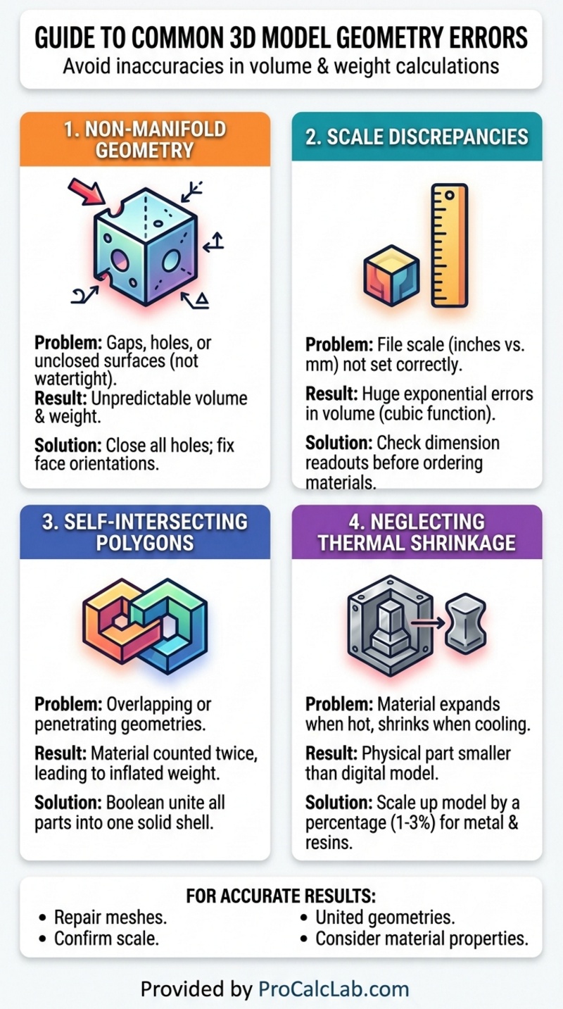
The core accuracy of any volume or weight calculation depends entirely on the mathematical integrity of the uploaded digital file. Several common 3D modeling errors can severely distort the final readouts and lead to bad production decisions.
Non-manifold geometry stands as the most frequent culprit. A manifold model possesses a completely closed watertight outer surface. If a model features microscopic holes, flipped normal vectors, or interior faces that intersect awkwardly, the system cannot definitively determine what represents the solid inside versus the empty outside. This geometric confusion leads to highly erratic volume calculations. Always run complex CAD files through a dedicated mesh repair utility prior to formal evaluation.
Scale discrepancy causes massive exponential errors. Because volume relies on a cubic mathematical function, a seemingly small unit mistake radically alters the final outcome. Designing a part in inches but exporting the file as millimeters shrinks the bounding box by a factor of 25.4. However, that linear reduction shrinks the calculated volume by a factor of over 16,000. Always verify that the bounding box numbers align with physical reality before ordering expensive materials.
Self-intersecting polygons represent another major geometry failure. This error occurs when two separate 3D bodies are merged visually on screen but not mathematically united through boolean operations. The volume algorithm might count the overlapping interior space twice, artificially inflating the final weight estimate. Engineers must ensure all multi-part assemblies are fully merged into a single continuous outer shell before exporting to the final STL format for analysis.
Regarding metal mold making, thermal shrinkage must be accounted for. When casting molten metals or highly exothermic resins, the material expands when hot and visibly shrinks as it cools to room temperature. While the digital volume remains static, the physical volume will undoubtedly change. Engineers generally scale up the digital model by a specific shrinkage compensation factor usually between 1 and 3 percent depending on the specific alloy to ensure the final cooled part matches the intended dimensional specifications. This slight operational increase in digital size will naturally increase the calculated volume and weight requirements.
Literature
For deeper exploration into manufacturing properties, material science, and digital fabrication workflows, consult the following industry standards and reference texts.
- Machinery’s Handbook, 31st Edition. Industrial Press. A comprehensive guide covering metalworking operations, material properties, and global manufacturing standards.
- The 3D Printing Handbook: Technologies, design and applications. 3D Hubs. Detailed breakdowns of additive manufacturing constraints, support structures, and material behaviors.
- Materials Science and Engineering: An Introduction. William D. Callister. The foundational textbook on density, mechanical strength, and structural properties of engineering materials.
- Fundamentals of Modern Manufacturing: Materials, Processes, and Systems. Mikell P. Groover. Extensive technical coverage of traditional casting, CNC machining, and modern polymer processing.
- ASTM International Standard Specifications. Specific procedural documents governing the physical testing and density verification of commercial plastics and metallic alloys.

Markus Fletcher — Structural Design Specialist
Expert in structural integrity, 3D modeling, and applied mathematics. Markus focuses on creating precise tools for construction professionals and DIY engineers.


