Accessing reliable groundwater requires precise system management. Property owners must understand the exact capacity of their water source to ensure adequate pressure, plan for dry seasons, and perform routine maintenance. This comprehensive reference explains how to master system capacity, manage fluid reserves, and properly utilize the 3-dimensional estimation tool.


How to Use the Interactive Tool
The provided interactive interface simplifies complex geometry into a visual model. Users select their preferred measurement system. The Imperial option remains standard for North American properties. Next, choose the shape of the water storage. For standard drilled boreholes, the cylindrical option is appropriate. For hand-dug setups or rectangular cisterns, the rectangular shape applies.
- Step 1: Input the primary dimensions. For a cylinder, enter the casing diameter and total depth.
- Step 2: Set the static fluid level. This metric represents the distance from the top of the casing down to the liquid surface.
- Step 3: Adjust the fluid density. Standard fresh water defaults to 62.4 pounds per cubic foot.
- Step 4: Click the calculation button. The engine generates a 3-dimensional representation and outputs exact fluid mass and capacity. The interface displays total potential volume and current available reserve in gallons.
Volume Versus Yield
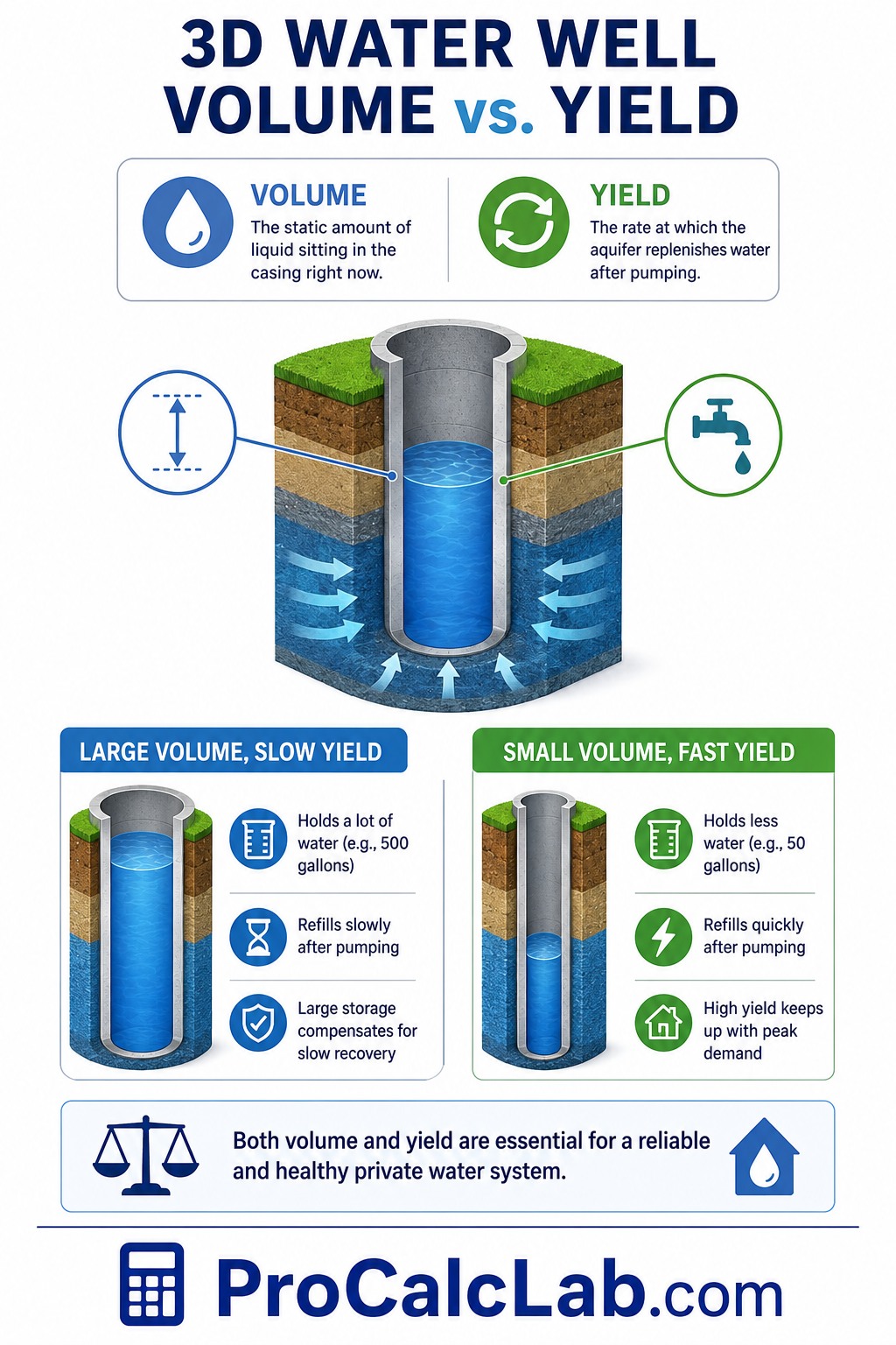
Many property owners confuse 2 critical metrics: volume and yield. Volume is the static amount of liquid sitting in the casing at any given moment. Yield is the rate at which the surrounding aquifer replenishes that liquid after pumping occurs. A deep borehole with a wide casing might hold 500 gallons. This acts as a massive storage tank. This large storage compensates for a slow recovery rate. Conversely, a narrow borehole might hold only 50 static gallons but possess a rapid yield that keeps up with peak household demand. Both numbers dictate the overall health of a private water system.
Why Exact Measurements Matter
Routine sanitization requires exact chemical dosing. A chlorine dose that is too small fails to eradicate harmful bacteria. A dose that is too large damages submersible pumps and takes 3 to 5 days to flush from the plumbing. Knowing the precise gallon count ensures the correct chemical ratio.
💧 Submersible pumps push liquid from the static level up to the pressure tank. Selecting a pump with excessive horsepower for a low-volume source leads to short-cycling. Short-cycling happens when the pump drains the casing faster than the aquifer recovers. This burns out the motor rapidly.
During extended dry spells, the water table drops. By recalculating the volume with a lower fluid level, property owners can adjust their daily consumption to avoid running the system dry.
The Mathematics of Capacity
The internal engine relies on established volumetric formulas. For cylindrical drilled boreholes, finding the base area is the 1st step.
Formula: V = π × r2 × h
- V = Volume
- π = 3.14
- r = Casing radius
- h = Height of the fluid column
Formula for radius: r = D / 2
For rectangular cisterns, the math requires straight dimensions.
Formula: V = L × W × H
- L = Length
- W = Width
- H = Liquid height
Practical Calculation Example
Consider a standard residential property with a 6-inch diameter drilled casing. The total depth = 200 feet. The static fluid level = 50 feet below the surface. Fluid column height = 200 – 50 = 150 feet.
- Casing diameter in feet = 6 / 12 = 0.5 feet.
- Radius = 0.5 / 2 = 0.25 feet.
- Base area = 3.14 × 0.25 × 0.25 = 0.2 square feet.
- Cubic volume = 0.2 × 150 = 30 cubic feet.
- 1 cubic foot = 7.48 gallons.
- Total static reserve = 30 × 7.48 = 224.4 gallons.
This property has 224 gallons in immediate reserve. Numbers are rounded down to practical minimums for safety margins.
Aquifer Types and Geology
Groundwater exists in 2 primary formations: unconfined and confined aquifers. Unconfined aquifers rest near the surface. Their levels fluctuate rapidly with seasonal rainfall. Shallow dug setups tap into these layers. Confined aquifers reside beneath impermeable rock or clay layers. Drilled setups penetrate these deep layers. Confined sources offer better protection against surface contamination and provide more stable static levels year-round.
Casing Materials and Dimensions
The casing material impacts the internal diameter and total storage capacity. Older systems often utilize steel casings. Steel provides extreme durability but eventually rusts. Modern installations heavily favor PVC piping. PVC resists corrosion and lasts for decades. Always use the internal diameter for calculations. A casing with a 6-inch external diameter might only measure 5.8 inches internally due to wall thickness. This small difference changes the total reserve significantly over a 300-foot depth.
The Role of the Pressure Tank
The underground setup does not deliver liquid directly to the faucet. The submersible pump pushes liquid into a pressure tank located inside the house. This tank contains a pressurized air bladder. When a faucet opens, the air bladder pushes fluid through the plumbing. The pump only turns on when the tank pressure drops below a specific threshold. This setup prevents the pump from starting every single time someone flushes a toilet. Knowing the total borehole capacity helps determine the correct pressure tank size. A system with a low reserve requires a massive pressure tank to store liquid above ground.
System Maintenance and Monitoring
Routine inspection prevents catastrophic system failures. Property owners must test fluid quality 1 time per year. Testing should check for coliform bacteria, nitrates, and heavy metals. Sudden changes in pressure often indicate a dropping static level or a failing pump. If the faucets begin sputtering air, the static level has likely dropped below the pump intake. This requires immediate investigation. A professional contractor can lower the pump deeper into the casing if the total depth allows.
Troubleshooting Common Capacity Issues
A sudden drop in available liquid stems from 3 common causes.
Cause 1: Clogged screen. Minerals build up on the metal screen at the bottom of the casing. This blocks liquid from entering the borehole. A contractor can clean this screen using acid treatments or mechanical surging.
Cause 2: Failed check valve. The check valve prevents liquid from flowing backwards into the ground after the pump shuts off. A broken valve causes the pump to run constantly.
Cause 3: Aquifer depletion. Extended droughts or heavy nearby agricultural pumping can lower the regional water table. The only solutions involve drilling a deeper hole or installing an above-ground storage cistern.
Drilling Methods and Their Impact on Storage
Contractors utilize 3 primary methods to create residential boreholes. The chosen method dictates the final diameter and the resulting storage capacity. Rotary drilling uses a rapidly spinning bit to crush rock. This method efficiently creates deep 6-inch holes through hard formations. Cable tool drilling repeatedly drops a heavy chisel bit to break the earth. This older method often utilizes larger 8-inch or 10-inch steel casings. A 10-inch casing holds nearly 3 times more reserve per foot than a 6-inch casing. Auger drilling works only in soft clay or sand and typically creates shallow, wide-diameter dug setups.
Water Quality in High-Volume Systems
Massive storage capacity presents unique challenges. When a borehole holds 1000 gallons but the household only uses 100 gallons per day, the liquid remains stagnant. Stagnant groundwater encourages the growth of iron bacteria. These harmless but annoying organisms create a thick orange slime. This slime coats the pump, clogs the plumbing, and causes foul odors. Systems with massive reserves and low turnover rates require frequent flushing to maintain pristine fluid quality. Property owners should periodically run an outdoor hose for 2 to 3 hours to cycle the entire reserve.
Hydrofracturing Low-Yield Boreholes
When a property suffers from both low static volume and minimal aquifer yield, hydrofracturing provides a viable solution. This process does not increase the physical volume of the casing. Instead, a contractor seals the borehole and injects fluid at 3000 pounds per square inch. This immense pressure blasts open existing microscopic fissures in the surrounding bedrock. Wider fissures allow groundwater to flow into the casing at a faster rate. A successful hydrofracturing procedure can increase yield by 50 % to 200 %. This upgraded recovery rate compensates for a small static casing reserve.
Understanding Head Pressure
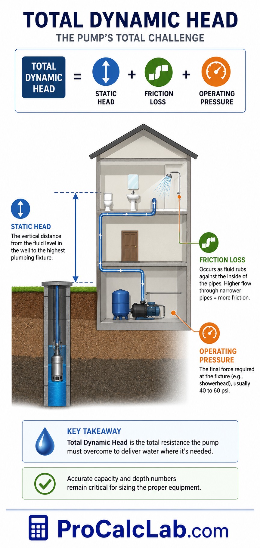
Moving fluid from deep underground into a 2nd-story bathroom requires overcoming immense physical forces. Total dynamic head represents the total resistance the pump must overcome.
Total Dynamic Head = Static Head + Friction Loss + Operating Pressure
Static head is the vertical distance from the fluid level to the highest plumbing fixture. Friction loss occurs as fluid rubs against the inside of the pipes. Pushing a high volume of liquid through a narrow pipe creates massive friction. Operating pressure is the final force required at the showerhead, usually 40 to 60 pounds per square inch. Accurate capacity and depth numbers remain critical for sizing the proper equipment.
Winterizing and Seasonal Changes
Cold climates demand specific management of fluid reserves. Frost lines can penetrate 4 to 6 feet below the surface. Any fluid standing above the frost line will freeze, expanding and shattering the casing. Pitless adapters solve this problem. A pitless adapter connects the vertical drop pipe to the horizontal house supply line deep underground, well below the freezing mark. The tool helps users determine exactly how much fluid sits below this critical frost line. During spring thaws, surface runoff can infiltrate poorly sealed casings. This introduces agricultural runoff or surface bacteria into the pristine reserve below.
Reference Data Tables
Table 1: Standard Borehole Diameter and Capacity per Foot
| Casing Diameter [inches] | Base Area [square feet] | Volume per Foot [gallons] |
|---|---|---|
| 2 | 0.02 | 0.16 |
| 3 | 0.05 | 0.37 |
| 4 | 0.09 | 0.65 |
| 5 | 0.14 | 1.02 |
| 6 | 0.20 | 1.47 |
| 7 | 0.27 | 2.00 |
| 8 | 0.35 | 2.61 |
| 10 | 0.55 | 4.08 |
| 12 | 0.79 | 5.88 |
| 14 | 1.07 | 8.00 |
| 16 | 1.40 | 10.44 |
| 24 | 3.14 | 23.50 |
| 36 | 7.07 | 52.88 |
| 48 | 12.57 | 94.00 |
| 60 | 19.63 | 146.88 |
Table 2: Household Fixture Daily Fluid Usage
| Fixture Type | Usage per Event [gallons] | Average Daily Total [gallons] |
|---|---|---|
| Standard Toilet Flush | 3 | 15 |
| Low-Flow Toilet Flush | 1.5 | 7.5 |
| Standard Shower [10 min] | 25 | 50 |
| Low-Flow Shower [10 min] | 15 | 30 |
| Bathtub Fill | 40 | 40 |
| Standard Washing Machine | 35 | 35 |
| High-Efficiency Washer | 15 | 15 |
| Dishwasher | 10 | 10 |
| Kitchen Sink [5 min] | 10 | 20 |
| Bathroom Sink [2 min] | 4 | 16 |
| Outdoor Hose [10 min] | 50 | 50 |
| Sprinkler System [30 min] | 150 | 150 |
| Car Wash | 100 | 100 |
| Water Softener Regeneration | 50 | 50 |
| Reverse Osmosis Waste | 10 | 10 |
Table 3: Common Disinfection Dosage based on Reserve
| Total Fluid Reserve [gallons] | Standard Household Bleach [cups] | Minimum Contact Time [hours] |
|---|---|---|
| 50 | 1.5 | 12 |
| 100 | 3 | 12 |
| 150 | 4.5 | 12 |
| 200 | 6 | 12 |
| 250 | 7.5 | 12 |
| 300 | 9 | 12 |
| 400 | 12 | 12 |
| 500 | 15 | 12 |
| 750 | 22 | 24 |
| 1000 | 30 | 24 |
| 1250 | 37 | 24 |
| 1500 | 45 | 24 |
| 1750 | 52 | 24 |
| 2000 | 60 | 24 |
| 2500 | 75 | 24 |
Table 4: Standard Pump Sizes based on Depth
| Motor Power [HP] | Maximum Effective Depth [feet] | Average Flow [GPM] |
|---|---|---|
| 0.5 | 50 | 10 |
| 0.5 | 100 | 5 |
| 0.75 | 100 | 10 |
| 0.75 | 150 | 7 |
| 1.0 | 150 | 12 |
| 1.0 | 200 | 8 |
| 1.5 | 200 | 15 |
| 1.5 | 250 | 10 |
| 2.0 | 250 | 20 |
| 2.0 | 300 | 12 |
| 3.0 | 300 | 25 |
| 3.0 | 400 | 15 |
| 5.0 | 400 | 40 |
| 5.0 | 600 | 20 |
| 7.5 | 600 | 30 |
Table 5: Pipe Friction Loss Rates per 100 Feet
| Flow Rate [GPM] | 1-Inch Pipe Loss [PSI] | 2-Inch Pipe Loss [PSI] |
|---|---|---|
| 5 | 0.8 | 0.1 |
| 10 | 2.9 | 0.2 |
| 15 | 6.1 | 0.3 |
| 20 | 10.4 | 0.5 |
| 25 | 15.7 | 0.7 |
| 30 | 22.0 | 1.0 |
| 35 | 29.4 | 1.3 |
| 40 | 37.7 | 1.7 |
| 45 | 47.0 | 2.1 |
| 50 | 57.3 | 2.5 |
| 60 | 80.8 | 3.5 |
| 70 | 108.1 | 4.6 |
| 80 | 139.1 | 5.9 |
| 90 | 174.0 | 7.4 |
| 100 | 212.6 | 9.0 |
Literature
- Groundwater and Wells by F. G. Driscoll
- Manual of Water Well Construction Practices by EPA
- Design of Small Water Systems by Joseph Salvato
- Practical Hydraulics by Melvyn Kay
- Water Supply and Pollution Control by Warren Viessman
- Standard Methods for the Examination of Water and Wastewater by APHA
- Hydrogeology Field Manual by Willis Weight
- Groundwater Hydrology by David Todd
- Residential End Uses of Water by AWWA Research Foundation
- The Home Water Supply by Stu Campbell

Markus Fletcher — Structural Design Specialist
Expert in structural integrity, 3D modeling, and applied mathematics. Markus focuses on creating precise tools for construction professionals and DIY engineers.