| Parameter | 1 Piece | Total |
| Weight, lbs | — | — |
| Volume, ft³ | — | — |
| Area, ft² | — | — |
| Cost | — | — |
Steel procurement requires accurate numbers. Estimating material weight, surface area, total volume, and complete project costs before placing a structural metal order prevents expensive waste and critical job site shortfalls. This interactive tool simplifies the layout process by providing real-time dimensional outputs for three foundational structural shapes. Builders, fabricators, and designers can instantly toggle between measurement systems to generate clean data sheets for accurate bidding and material scheduling.


Table of Contents
Step-by-Step Instructions for Using Tool
The interface acts as a visual and mathematical sandbox. Every adjustment alters the dimensional matrix instantly. Follow this operational layout to extract accurate metrics for a bill of materials.
1. Select the Core Structural Profile
Three primary structural buttons sit at the top of the panel. Click Channel, Angle, or I-Beam to load the corresponding profile geometry. Selecting a profile modifies the structural math model and shifts the active 3D view canvas to display the selected profile blueprint automatically.
2. Define the Measurement System
The system selector controls the measurement environment. By default, the tool opens in the Imperial system, which uses feet, inches, and pounds. If a project requires international metrics, switch the dropdown to Metric to convert all inputs and outputs to meters, millimeters, and kilograms. Changing the system recalculates existing entries into the new units instantly without resetting the inputs.
3. Choose the Structural Material
The material dropdown configures the density values required to calculate exact weights. The default option is standard structural carbon steel. Users can also select stainless steel, aluminum, copper, or brass. The calculator automatically adjusts the underlying density constant to match the physical properties of the chosen metal group.
4. Configure Physical Dimensions
Four primary dimension fields determine the physical size of the metal profile. Use the slider bars for fast adjustments or type precise values directly into the numerical boxes on the right.
- Length: Determines the linear span of each individual piece. Measured in feet for imperial or meters for metric.
- Height: Controls the overall vertical distance across the main section profile. Measured in inches or millimeters.
- Width: Establishes the horizontal width of the profile flanges or legs. Measured in inches or millimeters.
- Thickness: Sets the material wall thickness across the web and flanges. Measured in fractions of an inch or millimeters.
5. Input Project Volume and Budget Metrics
The final two input lines expand individual material dimensions into total project totals. Adjust the Quantity slider to match the total number of identical pieces required for assembly. Set the Price slider to the current local market rate per unit length, which means price per linear foot in imperial mode or price per meter in metric mode.
6. Utilize the 3D Visualizer and Export Features
The central view pane provides a live 3D representation of the configured profile. Click and drag within the canvas to rotate the model and view the flange connections from any angle. Below the 3D preview, a detailed SVG blueprint displays exact dimensions with dimension lines. Once the outputs match the project requirements, click the Download Result button to capture a high-resolution PNG screenshot of the entire calculator panel for project submittals.
Understanding Structural Profiles and Applications
Each profile shape behaves differently under load conditions. Selecting the correct shape depends on the direction of forces, weight limitations, and joining requirements.
American Standard Channels
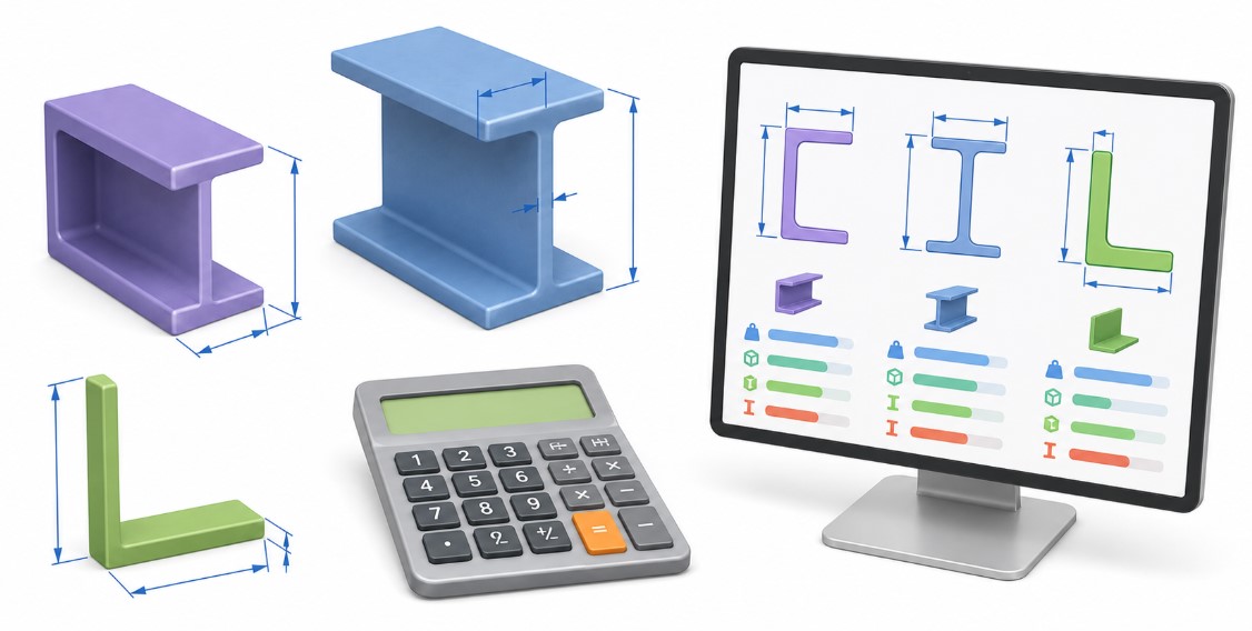
Often referred to as C-channels, these profiles feature a flat back web with two parallel flanges extending outward on one side. This asymmetrical design makes channels perfect for structural framing where one side must remain entirely flush against walls or decking. Channels offer strong bending resistance along their major axis but require proper bracing to prevent twisting under heavy torsional loads. Common applications include building stair stringers, trailer frames, roof trusses, and vehicle chassis supports.
Wide-Flange and American Standard I-Beams
I-beams represent the backbone of heavy commercial construction. The profile consist of a central vertical web that resists shear forces, balanced by two wide horizontal flanges that counteract intense bending moments. The symmetrical layout maximizes load capacity while minimizing total steel weight. These beams are designed to span long open distances under heavy floor or roof loads. Fabricators use I-beams for main structural pillars, bridge girders, floor joists, and overhead crane rails.
Structural Steel Angles
Commonly called L-brackets or angle iron, these elements consist of two legs meeting at a perpendicular ninety-degree angle. Angles come in equal leg configurations, where both legs share identical widths, or unequal leg variations. Angles serve as excellent bracing components, light structural frames, trim elements, and connection brackets that tie larger beams to primary columns. Their simple geometry allows for quick cutting, drilling, welding, and field modification using standard ironworking tools.

Reference Data: Standard Imperial Steel Profile Dimensions
The following tables outline common commercial dimensions used across the North American steel market. These numbers provide standard values to enter into the calculator for realistic project planning.
Standard C-Channel Reference Values
| AISC Size Designation | Flange Width by Web Height | Weight Per Linear Foot |
|---|---|---|
| C3 x 4.1 | 1.41 in x 3.00 in | 4.1 lbs |
| C4 x 5.4 | 1.58 in x 4.00 in | 5.4 lbs |
| C5 x 6.7 | 1.75 in x 5.00 in | 6.7 lbs |
| C6 x 8.2 | 1.92 in x 6.00 in | 8.2 lbs |
| C8 x 11.5 | 2.26 in x 8.00 in | 11.5 lbs |
| C10 x 15.3 | 2.60 in x 10.00 in | 15.3 lbs |
| C12 x 20.7 | 2.94 in x 12.00 in | 20.7 lbs |
| C15 x 33.9 | 3.40 in x 15.00 in | 33.9 lbs |
Standard Wide-Flange I-Beam Reference Values
| AISC Size Designation | Flange Width by Total Depth | Weight Per Linear Foot |
|---|---|---|
| W4 x 13 | 4.06 in x 4.16 in | 13 lbs |
| W6 x 15 | 5.99 in x 5.03 in | 15 lbs |
| W8 x 18 | 8.14 in x 5.25 in | 18 lbs |
| W10 x 22 | 10.17 in x 5.75 in | 22 lbs |
| W12 x 26 | 12.22 in x 6.49 in | 26 lbs |
| W14 x 30 | 13.84 in x 6.73 in | 30 lbs |
| W16 x 36 | 15.86 in x 6.99 in | 36 lbs |
| W18 x 50 | 17.99 in x 7.49 in | 50 lbs |
Standard Equal Leg Angle Reference Values
| AISC Size Designation | Leg Dimensions by Thickness | Weight Per Linear Foot |
|---|---|---|
| L2 x 2 x 1/8 | 2 in x 2 in x 0.125 in | 1.65 lbs |
| L2.5 x 2.5 x 3/16 | 2.5 in x 2.5 in x 0.187 in | 3.07 lbs |
| L3 x 3 x 1/4 | 3 in x 3 in x 0.250 in | 4.90 lbs |
| L4 x 4 x 1/4 | 4 in x 4 in x 0.250 in | 6.60 lbs |
| L4 x 4 x 1/2 | 4 in x 4 in x 0.5 in | 12.80 lbs |
| L5 x 5 x 3/8 | 5 in x 5 in x 0.375 in | 12.30 lbs |
| L6 x 6 x 1/2 | 6 in x 6 in x 0.5 in | 19.60 lbs |
| L8 x 8 x 1/2 | 8 in x 8 in x 0.5 in | 26.40 lbs |
Mathematical Foundation of Steel Profile Estimation
The calculator isolates cross-sectional profile logic into straightforward geometric steps. Knowing the mathematics helps confirm structural reports manually.
Cross-Sectional Area Calculations
📐 To establish volume, the application first determines the two-dimensional surface area of the metal face. It strips away overlapping dimensional areas at connection junctions to maintain accurate volume counts.
For a standard channel or I-beam profile, the area formula splits the system into three simple rectangles: the central vertical web and two horizontal flanges. The calculation reads:
A = 2 * W * T + (H – 2 * T) * T
For an L-shaped structural angle profile, the calculation accounts for a single intersection corner where the vertical and horizontal legs meet:
A = W * T + (H – T) * T
Volume and Total Mass Conversion
Once the system determines the profile cross-sectional area, it calculates the raw volume by extending that area across the total length of the piece. In imperial mode, cross-sectional values in square inches are divided by 144 to convert them into square feet before multiplying by the length. The volume formula is:
V = (A / 144) * L
After finding the total volume, the calculator multiplies it by the density factor of the selected metal to determine the final weight of a single piece. For carbon steel, the default imperial density value is 490 pounds per cubic foot. The total weight formula is:
M = V * d
Surface Area and Exterior Coating Analysis
Calculating the total perimeter of the profile face is necessary to estimate exterior surface area for painting, galvanizing, or rust protection treatments. The total perimeter represents the length of the outer line wrapping around the entire profile shape. The surface area formula multiplies this perimeter by the total length and adds the two flat cut faces at the ends of the beam:
S = (P / 12) * L + 2 * (A / 144)
Real-World Project Scenario: Imperial Structural Walkthrough
To see how these principles work in practice, let us analyze a typical commercial framing installation scenario using standard American imperial values. This example illustrates how the calculator handles numbers behind the scenes.
Project Specifications and Inputs
Suppose a workshop build requires heavy-duty steel channels to support an overhead storage platform. The procurement plan requires the following inputs:
- Selected Profile: Channel
- Material Group: Carbon Steel, with a density of 490 lbs/ft³
- Length per piece: 15 feet
- Profile Height: 8 inches
- Profile Width: 3 inches
- Wall Thickness: 0.25 inches
- Total Material Volume: 12 pieces
- Local Market Cost: 18.50 dollars per linear foot
Manual Calculation Breakdown
First, find the cross-sectional area of the channel face using the rectangular area formula:
A = 2 * 3 * 0.25 + (8 – 2 * 0.25) * 0.25
A = 1.50 + (7.50) * 0.25
A = 1.50 + 1.88 = 3.38 square inches
Convert the square inches into square feet to match the density units:
Aft = 3.38 / 144 = 0.0235 square feet
Multiply by the individual length of a single beam to determine its volume:
V = 0.0235 * 15 = 0.3525 cubic feet
Calculate the final weight of one piece using the carbon steel density factor:
Mass = 0.3525 * 490 = 172.73 pounds per piece
Multiply this individual weight by the total order volume to find the total project shipping weight:
Total Mass = 172.73 * 12 = 2072.76 pounds
Calculate the financial metrics by multiplying the linear length by the price per foot:
Price per piece = 15 * 18.5 = 277.5 $
Total project order price = 277.5 * 12 = 3330 $
Plugging these values into the input fields yields identical results, rounding numbers to a clean layout for simple, accurate material ordering and logistical planning.
Practical Tips for Structural Steel Field Operations
Relying solely on ideal mathematical equations can create issues during field installation. Keep these practical variables in mind when finalizing your material orders.
Account for Cutting Waste and Drop Allowances
Structural steel is typically sold in standard stock lengths, such as 20, 40, or 60 feet. When cutting custom lengths for a project, the thickness of the saw blade, known as the kerf, removes a small amount of material with every cut. Repeated cuts can shorten the final pieces of steel. Always order an extra five to ten percent of raw material to account for cutting layouts, corner mitering, and field mistakes.
Verify Shipping Weight Limits and Equipment Capacities
The total weight value from the calculator is essential for planning project logistics. Truck beds, trailers, and forklifts have strict lifting and transport capacities. For instance, the example project batch weighs over one ton. Knowing the exact weight helps you arrange the right vehicle size and select appropriate rigging straps and cranes for safe offloading at the job site.
Plan for Surface Priming and Coating Costs
Unprotected carbon steel rusts quickly when exposed to moisture and air. Use the surface area output to determine exactly how much industrial primer, paint, or protective coating your project needs. Paint manufacturers list coverage rates in square feet per gallon. Matching this rating to the calculated surface area prevents multiple trips to the industrial paint supplier during mid-assembly operations.
References and Industry Standards
- American Institute of Steel Construction. Manual of Steel Construction. Fourteenth Edition. AISC, Chicago, 2011.
- ASTM International. Standard Specification for Carbon Structural Steel. Standard Designation A36/A36M-19. ASTM, West Conshohocken, 2019.
- Society of Automotive Engineers. Material Density Tables for Industrial Alloys. SAE HS-1086. Warrendale, 2015.
- Federal Highway Administration. Bridge Inspector Reference Manual: Structural Metal Geometry. U.S. Department of Transportation, Washington DC, 2018.

Markus Fletcher — Structural Design Specialist
Expert in structural integrity, 3D modeling, and applied mathematics. Markus focuses on creating precise tools for construction professionals and DIY engineers.