A parallelogram is one of the most versatile and frequently encountered shapes in physical design, architecture, and structural framing. While standard squares and rectangles dominate basic floor plans, introducing an angle changes the dynamic entirely. Slanted lines are essential for roof pitches, custom decking patterns, angled property boundaries, and intricate masonry layouts. However, stepping away from perfect ninety-degree corners introduces significant mathematical challenges. Guessing dimensions or relying on rough estimates almost always results in wasted material, gaping joints, or unstable structures. This interactive animated tool removes the guesswork by instantly generating exact dimensions, true working heights, and spatial representations for any angled quadrilateral.


Table of Contents
Navigating the Animated Interface
The workspace provides an intuitive, highly visual approach to structural math. Instead of staring at static equations, users manipulate live data points to see exactly how geometric changes affect the physical footprint of an object. The system is divided into clear functional zones, starting with the input panel and ending with a detailed digital blueprint.
Input Sliders and Numeric Fields
Precision begins with accurate baseline numbers. The control panel features a series of synchronized adjustment bars and manual text fields. Shifting a slider left or right offers a quick way to visualize structural changes in real time. For exact plan specifications, typing dimensions directly into the numeric boxes locks in the precise measurements required by the blueprint.
- Base Dimension a: This dictates the primary bottom and top boundary lengths. It is the foundational anchor line for the entire shape.
- Side Dimension b: This controls the length of the slanted left and right borders. It represents the physical length of the material needed for the edge, not the vertical space it occupies.
- True Height h: This is the strict vertical drop between the top and bottom parallel lines. Changing the height forces the tool to automatically recalculate the main slant angle.
- Corner Angle α: This defines the internal slant. Setting this to ninety creates a standard rectangle. Reducing the number sharpens the shape, pushing it closer to the ground and stretching its overall footprint.
Real-Time Spatial Rendering
Above the mathematical controls sits a dynamic three-dimensional viewport. The application generates a solid geometric model based on the active dimensions. In accordance with modern display preferences, this 3D visualization floats on a clean, transparent background by default, ensuring the model is the sole focal point without distracting color blocks. Users can grab and rotate the object using a mouse or touch screen to inspect the shape from a bird-eye view or a flat profile profile. This spatial awareness is crucial when attempting to understand how an angled surface will interact with surrounding walls or property lines.
The Two-Dimensional Blueprint Canvas
Below the numeric results table is a flat drafting layout. This canvas draws the exact shape to scale, highlighting the intersection of the primary corner-to-corner diagonals with dashed indicators. It serves as a visual confirmation for the builder before any physical cuts occur on the job site. The system even automatically adjusts its internal grid scale to prevent extreme angles from clipping outside the viewing box.
Field Application: Planning a Custom Slanted Deck
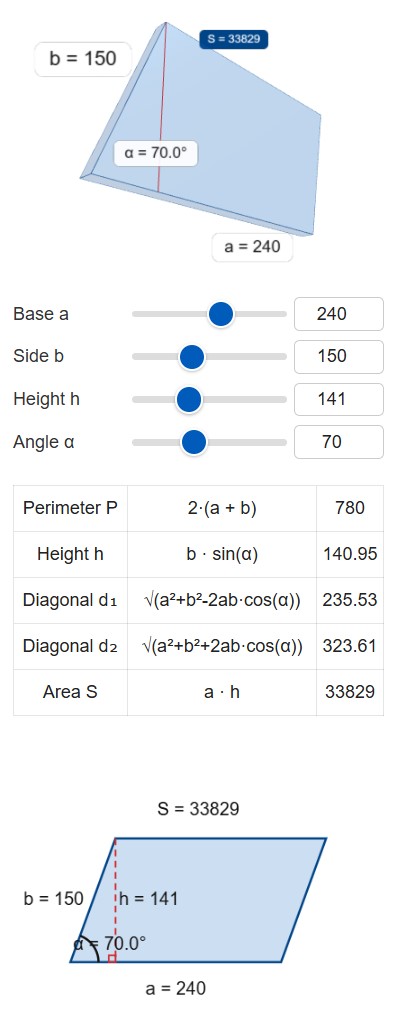
🏕 Theory is only useful when applied to real-world tasks. Consider a scenario where a landscaping crew is framing a custom angled timber deck to match the exact slant of an unusual property boundary. The architectural plans specify imperial units. The main ledger board attached to the house is 240 inches long. The side border runs for 150 inches along the slanted property line. The designated corner slant is exactly 70 degrees.
Entering these values into the system immediately reveals the true scope of the project:
- Base Length a: 240 inches
- Slanted Side b: 150 inches
- Corner Angle α: 70 degrees
The system instantly processes the trigonometry. First, the perimeter calculation shows that the crew needs 780 linear inches of outer rim joist material. Next, the tool provides the true vertical height. Even though the side board is 150 inches long, the sharp angle means the deck only extends 141 inches away from the house in a strict perpendicular line. This distinction is vital for knowing where the foundational concrete footings must be placed.
The total surface area calculates out to 33840 square inches. Dividing that massive number by 144 converts the footprint into a standard 235 square feet. This area metric is precisely what the contractor needs to order the correct volume of composite decking boards and hidden fasteners.
📝 Finally, the tool outputs the two internal diagonal lengths: 232 inches for the short span and 323 inches for the long span. When the framing crew builds the outer skeleton, they will pull a tape measure between the opposing corners. If the tape reads exactly 232 and 323 inches respectively, the frame is perfectly aligned and locked into the required 70-degree slant. If the numbers deviate, the frame is racking and must be physically bumped into proper alignment before the surface decking is attached.
Essential Structural Formulas
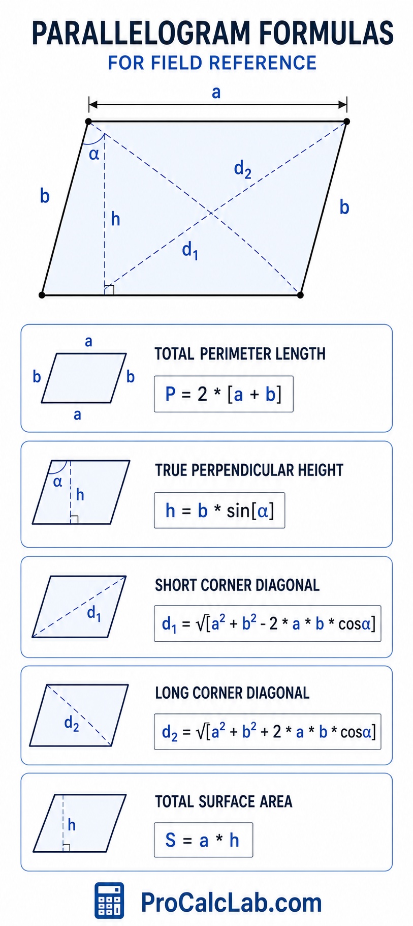
Understanding the math behind the interface provides confidence in the field. These equations govern the geometric behavior of all four-sided parallel shapes. The formulas are presented using standard mathematical notation adapted for clean, universal reading.
Total Perimeter Length:
P = 2 * [a + b]
True Perpendicular Height:
h = b * sin[α]
Short Corner Diagonal:
d1 = √[a2 + b2 – 2 * a * b * cosα]
Long Corner Diagonal:
d2 = √[a2 + b2 + 2 * a * b * cosα]
Total Surface Area:
S = a * h
Trade Reference Tables for Rapid Estimation
Professional drafters and estimators often rely on standard look-up tables for rapid budgeting before precise plans are finalized. The following charts provide benchmark data for various shape configurations.
Table 1: Slant Angle Height Reduction Multipliers
This table illustrates how the corner angle diminishes the true working height of a shape relative to the physical length of the slanted side piece. Multiplying the side length by the given factor provides a rapid height estimate.
| Working Corner Slant | Height Efficiency Factor | Visual Profile Style |
|---|---|---|
| 90° Square | 1.000 | Maximum Vertical Reach |
| 85° Slight Lean | 0.996 | Nearly Imperceptible Slant |
| 80° Minor Slant | 0.984 | Subtle Architectural Lean |
| 75° Standard Pitch | 0.965 | Common Rafter Angle |
| 70° Deep Pitch | 0.939 | Aggressive Roof Line |
| 60° Equilateral Base | 0.866 | Standard Chevron Joint |
| 50° Sharp Drop | 0.766 | Elongated Diamond Form |
| 45° Half Square | 0.707 | Perfect Miter Cut Intersection |
| 30° Low Profile | 0.500 | Flat Ground Paving Accent |
| 20° Extreme Lay | 0.342 | High Waste Custom Inlay |
Table 2: Material Scrap Estimator for Angled Cuts
Taking square sheet goods like plywood or drywall and cutting them into slanted configurations generates unavoidable triangular offcuts. This table provides a percentage markup to add to standard material orders to account for the geometric scrap.
| Design Angle α | Perimeter Waste Severity | Required Order Markup |
|---|---|---|
| 85° – 90° | Minimal End Trimming | Add 5 % |
| 75° – 84° | Slight Wedge Loss | Add 8 % |
| 65° – 74° | Standard Angle Scrap | Add 12 % |
| 55° – 64° | Moderate Corner Offcuts | Add 15 % |
| 45° – 54° | High Triangular Waste | Add 20 % |
| 35° – 44° | Severe Sheet Loss | Add 25 % |
| 25° – 34° | Extreme Layout Inefficiency | Add 35 % |
| 15° – 24° | Massive Custom Fitting | Add 50 % |
Table 3: Common Architectural Dimension Sets
Certain base and side combinations are frequently used in commercial and residential trades due to the standard manufacturing lengths of raw lumber, steel, and masonry products.
| Project Type Focus | Main Base a | Slanted Side b | Internal Angle |
|---|---|---|---|
| Masonry Accent Brick | 8 in | 4 in | 60° |
| Ceramic Floor Tile | 12 in | 12 in | 75° |
| Heavy Concrete Paver | 24 in | 18 in | 65° |
| Raised Garden Bed Frame | 48 in | 36 in | 80° |
| Standard Custom Decking | 144 in | 96 in | 70° |
| Residential Carport Roof | 240 in | 120 in | 75° |
| Angled Parking Lot Grid | 216 in | 108 in | 60° |
| Commercial Awning Frame | 300 in | 150 in | 55° |
| Agricultural Barn Extension | 480 in | 240 in | 70° |
Table 4: Internal Span Ratios
The relationship between the long and short corner-to-corner spans determines the structural rigidity of the shape. Shapes with highly uneven cross-spans require extra internal bracing to prevent wind or weight from causing structural collapse.
| Layout Angle | Short Span Ratio | Long Span Ratio |
|---|---|---|
| 90° | 1.00 Base Unit | 1.00 Base Unit |
| 80° | 0.91 Base Unit | 1.08 Base Unit |
| 70° | 0.82 Base Unit | 1.16 Base Unit |
| 60° | 0.73 Base Unit | 1.24 Base Unit |
| 50° | 0.64 Base Unit | 1.32 Base Unit |
| 40° | 0.54 Base Unit | 1.39 Base Unit |
| 30° | 0.43 Base Unit | 1.45 Base Unit |
The Critical Importance of the Height Dimension
One of the most frequent errors made by novice builders is confusing the length of the slanted boundary piece with the true vertical height of the shape. If a floor plan calls for a slanted extension that reaches ten feet away from a wall, purchasing ten-foot floor joists will result in a structure that falls short of the target mark. Because the joists are installed at an angle, their vertical reach is diminished by the pitch. The calculator instantly highlights this discrepancy. By locking in a specific height requirement, the system will back-calculate exactly how long the physical side lumber must be to hit that distant mark while maintaining the specified slant.
💻 The interface includes a dedicated export mechanism designed for seamless field integration. Clicking the download control captures the current state of the entire calculation box. This freezing process records the three-dimensional object rotation, the numerical table, and the two-dimensional blueprint view into a single high-resolution image file. Project managers routinely save these files to attach directly to client submittals, materials purchase orders, or digital job site dossiers. Providing the framing crew with a printed visual reference that clearly displays all four boundary lengths and the two crossing diagonal checks eliminates communication errors and ensures the raw materials are assembled exactly as designed.
Mitigating Layout Creep
Layout creep occurs when a tiny measurement error at the starting point of a large project slowly magnifies over distance. In a slanted grid, such as an angled parking lot or a large format flooring layout, being off by just one degree at the corner vertex can cause the final row to miss its target alignment by several inches. The precision generated by the calculator combats this issue. By utilizing the exact diagonal measurements rather than trying to measure a severe angle with a small hand tool, installers can set giant structural boundaries with perfect mathematical accuracy. Pinning the four corners using the diagonal spans guarantees the underlying geometry is locked tight before the interior grid work begins.
Literature
- Merritt, F. S., Ricketts, J. T. Building Design and Construction Handbook. 6th Edition. McGraw-Hill Professional, 2000.
- Feirer, J. L., Hutchings, M. D. Carpentry and Building Construction. Glencoe/McGraw-Hill, 2010.
- Blandford, P. W. The Practical Guide to Carpentry. Tab Books, 1984.
- Simmons, H. L. Construction: Principles, Materials, and Methods. 7th Edition. John Wiley and Sons, 2001.
- Alexander, D. C. Applied Mathematics for the Construction Trades. 3rd Edition. Cengage Learning, 2018.

Markus Fletcher — Structural Design Specialist
Expert in structural integrity, 3D modeling, and applied mathematics. Markus focuses on creating precise tools for construction professionals and DIY engineers.


