Planning a new building project requires accurate material estimation to keep budgets under control and prevent costly delays. Pouring a foundation involves coordinating heavy trucks, managing precise timing, and ensuring enough raw materials are on site. Running short on concrete in the middle of a pour creates a weak cold joint. Ordering too much wastes money. This tool eliminates the guesswork by providing exact volume measurements and material breakdowns for various base structures.



📝 Every construction site presents unique challenges. Soil density, frost lines, and structural load dictate the exact type of base required. Whether setting up a small backyard storage shed or engineering a massive commercial warehouse, getting the ground-level math right dictates the success of the entire structure above it. This guide breaks down how to calculate materials, how to operate the estimation tool, and what essential factors impact the final mix.
Table of Contents
Understanding Common Foundation Types
Construction projects typically rely on one of three main base designs. Choosing the right one depends on local building codes, soil bearing capacity, and the overall weight of the planned structure.
Strip Footings
Strip designs form a continuous line of support beneath load-bearing walls. Builders excavate a trench around the perimeter of the planned structure and fill it with reinforced concrete. This method works perfectly for residential homes and lighter commercial buildings built on stable, well-draining soil. The width and depth of the strip distribute the wall weight across a larger surface area, preventing uneven settling.
Solid Slabs
Slab-on-grade construction involves pouring a single thick layer of concrete directly over prepared ground. This style serves double duty as both the structural base and the ground floor of the building. Slabs excel in warmer climates where deep ground freezing poses no threat. Garages, workshops, and modern residential homes frequently utilize slabs due to their relatively fast preparation time and excellent durability.
Pile Systems
When topsoil lacks the strength to support a building, builders must drill down to find solid bedrock or dense earth. Pile systems consist of deep vertical columns placed at strategic load points. These columns transfer the building weight deep underground. Coastal properties, swampy areas, and massive high-rise structures rely heavily on this method to prevent sinking.
Operating the Interactive Estimator
The interactive estimator provides rapid material calculations based on specific project dimensions. The interface relies on visual drawing tools and simple sliders to adjust parameters dynamically.

Selecting the Structural Plan
Begin by choosing the core structure type from the top menu. Clicking Strip, Slab, or Pile changes the available input fields and adjusts the interactive drawing board. Ensure the toggle switch is set to Imperial to calculate measurements in feet, inches, cubic yards, and pounds.
Drawing the Perimeter
For strip and slab designs, an interactive grid allows for custom shape creation. The initial shape appears as a standard square. Clicking on any perimeter line adds a new anchor point. Dragging these anchor points alters the geometric footprint of the building. The on-screen measurements update immediately to reflect the new wall lengths in feet. This visual approach easily accommodates L-shaped buildings, bay windows, or complex angled walls.
Setting Dimensions via Sliders
Below the drawing board, a series of sliders fine-tune the vertical dimensions. Dragging the slider handle or typing directly into the number box updates the entire calculation instantly.
- Thickness: Applies to strip designs. This determines how wide the concrete trench is from the inner edge to the outer edge.
- Depth: Sets the vertical height of the poured concrete. For slabs, this is the floor thickness. For strips, it represents how deep the trench goes into the ground.
- Pile Count: Specifies the total number of vertical columns required for the grid.
- Diameter: Sets the width of each drilled hole for pile columns.
- Pile Length: Determines how deep each column extends into the earth.
Material Cost Inputs
Concrete can be ordered pre-mixed from a batch plant or mixed on site using raw materials. The tool calculates on-site mixing requirements based on standard structural concrete ratios. Adjusting the price sliders for Cement, Sand, and Gravel provides a total estimated material cost. Call local quarries or hardware suppliers to get current market rates per yard or bag, then input those numbers to generate an accurate project budget.
Practical Example: Pouring a Workshop Slab
Consider a practical scenario. A homeowner plans to build a dedicated woodworking shop in the backyard. The design calls for a simple rectangular slab measuring 20 feet wide by 30 feet long. The floor needs to support heavy machinery, so a thickness of 0.5 feet is required.
First, the user selects Slab from the main menu. On the drawing grid, they adjust the anchor points until the shape reflects a 20 by 30 rectangle. Next, they adjust the Depth slider to 0.5. The calculator instantly processes the underlying math.
The total volume emerges as 11.11 cubic yards. Knowing the volume is only the first step. If the builder decides to mix the concrete manually using a portable mixer, they need raw material quantities. The tool breaks down this 11.11 cubic yard total into precise components based on standard ratios.
For this specific slab, the output indicates a need for approximately 5222 pounds of Portland cement, 4.7 cubic yards of sharp sand, and 9.2 cubic yards of crushed gravel. The homeowner checks local prices: cement sits at 6 dollars per 100 pounds, sand runs 35 dollars per yard, and gravel costs 45 dollars per yard. Plugging these prices into the bottom sliders reveals the total raw material budget before formwork and rebar are factored in.
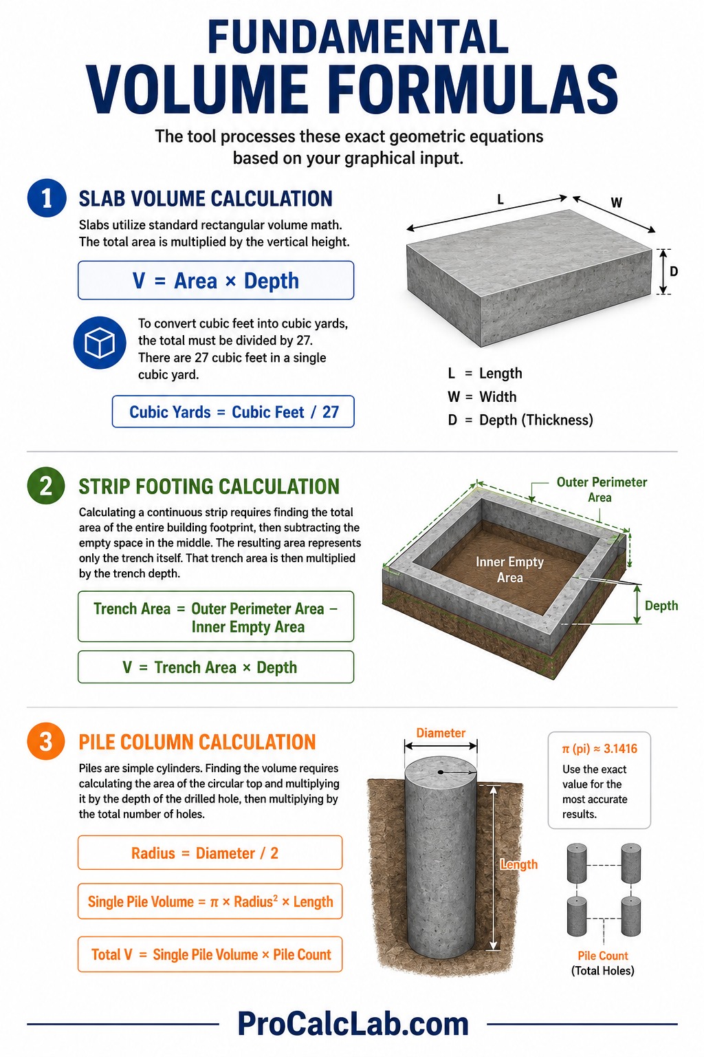
Fundamental Volume Formulas
Understanding the math behind the interface helps verify orders and catch potential measurement errors. The tool processes these exact geometric equations based on the user’s graphical input.
Slab Volume Calculation
Slabs utilize standard rectangular volume math. The total area is multiplied by the vertical height.
V = Area × Depth
To convert cubic feet into cubic yards, the total must be divided by 27. There are 27 cubic feet in a single cubic yard.
Cubic Yards = Cubic Feet / 27
Strip Footing Calculation
Calculating a continuous strip requires finding the total area of the entire building footprint, then subtracting the empty space in the middle. The resulting area represents only the trench itself. That trench area is then multiplied by the trench depth.
Trench Area = Outer Perimeter Area – Inner Empty Area
V = Trench Area × Depth
Pile Column Calculation
Piles are simple cylinders. Finding the volume requires calculating the area of the circular top and multiplying it by the depth of the drilled hole, then multiplying by the total number of holes.
Radius = Diameter / 2
Single Pile Volume = π × Radius2 × Length
Total V = Single Pile Volume × Pile Count
Essential Material Proportions
Creating strong structural concrete requires precise ratios of cement, fine aggregate, coarse aggregate, and water. Too much water weakens the final cured state. Too much sand reduces structural integrity. The industry standard for heavy load-bearing foundations generally follows a specific numeric ratio.
🧱 A highly common structural mix follows a 1 to 2 to 3 proportion. This means one part Portland cement, two parts clean sand, and three parts crushed gravel by volume. Water gets added slowly until the mixture reaches a thick, workable consistency resembling thick oatmeal. The calculator utilizes industry-standard conversion weights to turn the final cubic yardage into these exact raw material requirements.
Reference Tables for Foundation Planning
The following tables provide crucial reference points for planning excavation, mixing materials, and managing curing times. Always consult local municipal building codes before finalizing any structural depth.
Table 1: Recommended Minimum Depth by Climate Zone
| Geographic Region | Average Frost Line Depth | Minimum Recommended Footing Depth |
|---|---|---|
| Deep South USA | 0 to 5 inches | 12 to 18 inches |
| South Atlantic | 10 to 15 inches | 18 to 24 inches |
| Pacific Southwest | 0 to 10 inches | 12 to 24 inches |
| Mid-Atlantic | 20 to 30 inches | 36 to 42 inches |
| Central Plains | 30 to 40 inches | 42 to 48 inches |
| Pacific Northwest | 15 to 25 inches | 30 to 36 inches |
| Mountain West | 40 to 50 inches | 54 to 60 inches |
| New England | 45 to 60 inches | 60 to 72 inches |
| Upper Midwest | 50 to 65 inches | 72 to 80 inches |
| Alaska Coastal | 70 to 100 inches | 120+ inches or specialized piles |
Table 2: Standard Concrete Mix Compressive Strength
| Ratio by Volume | Target Compressive Strength | Primary Application |
|---|---|---|
| 1 part cement, 3 parts sand, 6 parts gravel | 1500 to 2000 PSI | Non-structural fill, sub-bases, light footpaths |
| 1 part cement, 2.5 parts sand, 5 parts gravel | 2000 to 2500 PSI | Light residential pathways, small shed bases |
| 1 part cement, 2 parts sand, 4 parts gravel | 2500 to 3000 PSI | Standard residential footings, driveways, patios |
| 1 part cement, 2 parts sand, 3 parts gravel | 3000 to 3500 PSI | Heavy duty slabs, garage floors, structural walls |
| 1 part cement, 1.5 parts sand, 3 parts gravel | 3500 to 4000+ PSI | Commercial structural columns, heavy machinery pads |
| 1 part cement, 1 part sand, 2 parts gravel | 4500+ PSI | High-wear surfaces, specialized structural engineering |
Table 3: Estimated Cure Times and Usability
| Time Elapsed Since Pour | Percentage of Total Strength | Allowable Site Activity |
|---|---|---|
| 24 to 48 Hours | 15 to 20 % | Forms can be carefully stripped. No foot traffic. |
| 3 Days | 30 to 40 % | Light foot traffic allowed. Keep surface damp. |
| 7 Days | 65 to 70 % | Light vehicle traffic allowed. Framing can begin. |
| 14 Days | 80 to 85 % | Heavy equipment positioning allowed with caution. |
| 21 Days | 90 to 95 % | Normal construction activities fully authorized. |
| 28 Days | 99 to 100 % | Maximum design strength achieved. Ready for full load. |
Table 4: Common Steel Rebar Sizing Guide
| Rebar Designation | Nominal Diameter | Weight per Foot |
|---|---|---|
| Number 3 | 0.375 inches | 0.376 pounds |
| Number 4 | 0.500 inches | 0.668 pounds |
| Number 5 | 0.625 inches | 1.043 pounds |
| Number 6 | 0.750 inches | 1.502 pounds |
| Number 7 | 0.875 inches | 2.044 pounds |
| Number 8 | 1.000 inches | 2.670 pounds |
Tips for a Successful Concrete Pour
Accurate math forms the baseline of a good project. Executing the work requires attention to physical details on the job site.
Over-Order Slightly: Ground is rarely perfectly level, and trenches are never perfectly square. Excavation often removes slightly more dirt than planned. Always add a 5 to 10 percent buffer to the final volume calculation to account for ground irregularities and minor spillage. Running a quarter yard short at the end of a long day is a frustrating and expensive mistake.
Manage the Moisture: The chemical reaction that hardens cement requires water, but it does not require drying out. In fact, concrete that dries too quickly becomes brittle and prone to surface cracking. In hot weather, cover the fresh slab with plastic sheeting or mist it lightly with a hose for the first three days to slow down the evaporation process.
Consolidate and Vibrate: Pouring thick trenches traps thousands of tiny air bubbles against the wooden forms and around the steel rebar. These air pockets create weak spots known as honeycombing. Renting a mechanical concrete vibrator and running it slowly through the wet mix forces these air bubbles to the surface, resulting in a smooth, structurally sound wall.
Prepare the Base: Pouring expensive material onto soft mud guarantees future failure. Excavate down to undisturbed subsoil, then add a layer of compacted crushed stone. Run a mechanical plate compactor over the stone base until it feels as hard as asphalt. This gravel layer provides a stable working platform and promotes drainage away from the bottom of the slab.
Check Form Plumb and Square: Liquid rock applies immense outward pressure. Wooden forms must be braced heavily. A blowout during the pour wastes materials and ruins the timeline. Double-check that all corners measure perfectly square by pulling a tape measure diagonally across the corners. If the two diagonal measurements match exactly, the shape is a perfect rectangle.
Conclusion
Failing to plan implies planning to fail. When dealing with heavy construction materials, guessing volume leads to disastrous outcomes. By mapping out the perimeter, setting accurate depths, and calculating precise raw material needs, builders ensure their structures begin on a solid footing. Always verify numbers, account for local soil conditions, and prioritize proper curing techniques to guarantee a foundation that lasts for generations.
Literature
- American Concrete Institute. Building Code Requirements for Structural Concrete.
- Portland Cement Association. Design and Control of Concrete Mixtures.
- Kosmatka, S.H. and Wilson, M.L. Concrete Technology.
- International Code Council. International Residential Code for One- and Two-Family Dwellings.
- Mindess, S., Young, J.F., and Darwin, D. Concrete. Second Edition.

Markus Fletcher — Structural Design Specialist
Expert in structural integrity, 3D modeling, and applied mathematics. Markus focuses on creating precise tools for construction professionals and DIY engineers.