Creating electronic schematics used to require heavy desktop software installations, complex library management, and steep learning curves. For simple projects, educational demonstrations, or quick documentation, a lightweight browser-based drafting utility provides a much better solution. The Instant Schematic Design Builder allows anyone to sketch, edit, and export professional-grade circuit diagrams directly from a web browser. Designed with a mobile-friendly 340-pixel constraint, the workspace remains perfectly accessible on smartphones, tablets, and desktop monitors alike.

This reference manual details exactly how to operate the drafting interface, explains the function of each digital tool, and provides practical reference tables for common electronic components. The goal is to provide a straightforward roadmap from a blank canvas to a fully exported circuit diagram.
Table of Contents
Navigating the Design Workspace
The application interface is divided into three distinct operational zones. The top toolbar holds all the drafting instruments and component symbols. The central canvas acts as the main drawing board, featuring an invisible magnetic grid that ensures all components and wires align perfectly. The bottom control panel houses the file export options and canvas management commands.
The invisible grid is the most important feature of the canvas. Every time a component or a line is placed, it automatically snaps to this grid. This guarantees that a wire drawn from a resistor will perfectly intersect with the connection point of a transistor, eliminating frustrating millimeter-level misalignments.
Component Library and Drafting Tools Reference
The top toolbar contains ten specific instruments. Clicking any of these buttons activates the tool, highlighting it in orange. Once activated, clicking anywhere on the central canvas will place the selected item.
- Circle Tool: Draws a basic circle. This is often used to represent specialized input sources, custom test points, or to highlight a specific section of a complex circuit for educational purposes.
- Line Tool: Draws solid black lines representing copper wires. Wires connect the various components together. The tool requires a starting click and an ending click to drop a straight wire segment.
- Point Tool: Drops a solid black dot. In schematic drafting, a solid dot indicates that two crossing wires are physically connected. If two wires cross without a dot, they are completely separate paths.
- Arrow Tool: Places a directional arrow. Arrows are excellent for documenting signal flow direction, indicating off-page connections, or pointing to specific nodes that require voltage measurements.
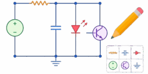
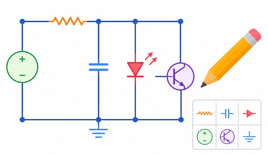
- Resistor Tool: Places a standard rectangular resistor symbol. Resistors limit the flow of electrical current. They are the most common component in any circuit design.
- Capacitor Tool: Places a symbol consisting of two parallel lines. Capacitors store small amounts of electrical energy and block direct current while allowing alternating current to pass.
- Inductor Tool: Places a symbol made of continuous semi-circles. Inductors store energy in a magnetic field and are heavily used in power supplies and radio frequency designs.
- Diode Tool: Places a triangle pointing to a straight line. Diodes act as one-way valves for electricity, ensuring current only flows in a single specified direction.
- Transistor Tool: Places a classic three-lead bipolar junction transistor symbol inside a circle. Transistors act as electronic switches or signal amplifiers.
- Text Tool: Opens an input field to place custom labels. Every component requires a label like R1 or C2, along with its specific value like 10k or 5V.
Canvas Controls and Export Functions
The bottom panel manages the overall drawing state and handles the generation of image files. Using these tools effectively speeds up the drafting process and ensures the final image integrates perfectly into technical documentation.
- Clear All Button: Instantly deletes every element on the canvas. This provides a fresh start but cannot be reversed.
- Undo Button: Removes the very last action performed. If a wire is drawn too long or a diode is placed in the wrong spot, this button rolls the canvas back one step.
- Delete Item Button: Removes a specific element. First, click a component on the canvas to select it. The element turns orange. Then, click this delete button to remove it without affecting the rest of the schematic.
- Rotate Button: Spins the selected component clockwise by 90 degrees. This allows resistors and capacitors to be placed both horizontally and vertically, which is absolutely necessary for neat circuit layouts.
- Export SVG Button: Downloads the schematic as a Scalable Vector Graphics file. This format uses mathematics instead of pixels to draw the image. It can be scaled to the size of a billboard without ever losing crispness, making it the absolute best choice for professional printing.
- Export Transparent PNG Button: Downloads a standard image file with no background color. This is highly recommended for modern websites because the circuit will seamlessly blend into both dark mode and light mode themes.
- Export White BG PNG Button: Downloads the schematic with a solid white background. This ensures maximum contrast and is the standard choice for generating images that will be printed on physical office paper.
- Fullscreen Button: Expands the drafting area to fill the entire monitor or mobile screen, removing browser tabs and system menus to provide a distraction-free engineering environment.

Step-by-Step Drafting Workflow
Building a readable schematic requires a logical sequence of actions. Attempting to draw wires before placing components usually leads to a messy and confusing diagram. Following a standard workflow yields professional results every time.
- First, identify the primary power rails. Place a text label for the positive voltage at the top of the canvas and a ground label at the bottom. Draw long horizontal lines extending from these labels to establish the power boundaries.
- Second, place the active components. Position transistors or integrated circuits in the center of the workspace. Use the rotation tool to ensure their connection pins face the correct directions.
- Third, add the passive components. Drop resistors, capacitors, and diodes around the active components. Leave plenty of empty white space between symbols. Crowded schematics are very difficult to read.
- Fourth, route the wires. Select the line tool and connect the component pins. Keep all wires strictly vertical or horizontal. Never draw diagonal wires in a professional schematic. If a wire needs to change direction, use two lines to create a clean 90-degree corner.
- Finally, apply text labels. Select the text tool and mark every single component with a unique identifier and a practical value. Place the text near the component, but ensure it does not overlap any wires or symbols.
Practical Electronic Reference Data
When drafting schematics, using standard component identifiers and practical values makes the diagram universally understandable. The following tables provide essential reference data for populating circuit diagrams accurately.
Standard Component Designators and Functions
Every component on a schematic must have a unique alphanumeric label. The letter indicates the type of component, and the number indicates its sequence in the circuit.
| Schematic Letter Code | Component Type | Practical Circuit Function |
|---|---|---|
| R | Resistor | Limits current flow and sets specific voltage levels |
| C | Capacitor | Filters power supply noise and blocks steady DC voltage |
| D | Diode | Forces electricity to flow in only one direction |
| Q | Transistor | Amplifies weak signals or acts as an electronic switch |
| L | Inductor | Stores energy magnetically and blocks high-frequency noise |
| U or IC | Integrated Circuit | Performs complex logic, timing, or processing tasks |
| J or P | Connector / Plug | Provides a physical interface for external wires |
Common Component Values for Practical Design
While theoretical math can produce highly specific component values, practical electronics rely on standard, widely available parts. Rounding to these common values makes circuits much easier to build.
| Component Category | Highly Common Values | Typical Real-World Application |
|---|---|---|
| Pull-up / Pull-down Resistors | 10k Ohms | Keeping digital logic pins stable |
| LED Current Limiting Resistors | 220 to 330 Ohms | Preventing standard indicator LEDs from burning out |
| Power Supply Filter Capacitors | 100uF to 1000uF | Smoothing out heavy voltage drops during power spikes |
| Digital IC Bypass Capacitors | 100nF | Providing instant localized power to fast-switching chips |
| Standard Rectifier Diodes | 1N4007 | Converting AC wall power into usable DC power |
| Small Signal NPN Transistors | 2N3904 or BC547 | Switching small relays or amplifying audio signals |
| Power MOSFET Transistors | IRFZ44N | Driving heavy motors or high-power lighting arrays |
Standard System Voltage Levels
Modern electronic circuits generally operate within a few standardized voltage tiers. Labeling power rails clearly with these values prevents catastrophic hardware damage.
| Voltage Level | Common Device Category | Practical Description |
|---|---|---|
| 3.3 Volts | Modern Microcontrollers | Standard for modern processors, sensors, and memory chips |
| 5.0 Volts | Classic Digital Logic | Traditional USB power and standard hobbyist electronics |
| 12.0 Volts | Automotive and Motors | Used for heavy loads, cooling fans, and LED light strips |
| 24.0 Volts | Industrial Control Systems | Standard for factory automation and large 3D printer beds |
Universal Schematic Layout Rules
A well-drawn schematic tells a clear story about how electricity moves through a system. To ensure the diagram is easy to read, industry professionals follow a strict set of visual rules.
⚡ Signal flow should always move from left to right. Inputs, such as microphones, sensors, or power jacks, belong on the far left side of the canvas. The signal should be processed through the central components and eventually reach the outputs, such as speakers, motors, or data transmitters, on the far right side.
Voltages should always flow from top to bottom. The highest positive voltage rail belongs at the very top of the drawing. The ground return line belongs at the very bottom. Components should be arranged vertically between these two rails so that current visually cascades downwards through the circuit.
Wire intersections require careful attention. If two wires must cross paths without making an electrical connection, simply draw one line directly over the other. If the crossing wires must connect electrically, the junction must be marked with a heavy solid dot using the Point Tool. To completely avoid confusion, many designers refuse to use four-way crossing connections. Instead, they stagger the connections into two separate three-way junctions, making the electrical intent unmistakable.
Literature
- Horowitz, Paul, and Winfield Hill. The Art of Electronics. Cambridge University Press, 2015.
- Platt, Charles. Make: Electronics. Maker Media, 2015.
- Gibilisco, Stan. Teach Yourself Electricity and Electronics. McGraw-Hill Education, 2011.
- Scherz, Paul, and Simon Monk. Practical Electronics for Inventors. McGraw-Hill Education, 2016.

David Parry — Senior Engineering Analyst
Specializing in electronics and physics-based simulations with 20+ years of engineering experience. David ensures the mathematical and physical accuracy of the tools at ProCalcLab.