| Uniformity | -- |
| Diffuser Loss | -- |
| Output Lumens | -- |
| Illuminance | -- |
| Junction Temp | -- |
| Lifespan L70 | -- |
| Color Tint Shift | -- |
LED lighting is widely marketed as a permanent illumination solution. Packaging claims often highlight 50000 hours of continuous operation. Real-world applications tell a completely different story. Strips lose brightness, shift in color tone, or fail entirely long before reaching that promised milestone. The primary culprit is poor thermal management combined with mismatched components. The LED Matrix Longevity and Burnout Predictor takes the guesswork out of lighting installations. It allows builders, interior designers, and hobbyists to test physical variables before purchasing expensive materials. Detailed understanding of these degradation mechanics helps in building reliable light fixtures.


Table of Contents
The Mechanics of Diode Failure
🌡 Heat destroys electronic components. Light-emitting diodes generate illumination by pushing electrical current across a microscopic semiconductor junction. This process is inherently inefficient because it releases a massive amount of thermal energy. If this heat cannot escape into the surrounding environment, the internal temperature of the chip rises rapidly. The internal heating parameter is referred to as the junction temperature.
A basic rule of semiconductor thermodynamics states that exceeding optimal operating temperatures by 10 degrees reduces the component lifespan by 50 %. If a chip is designed to run at 140 F, pushing it to 160 F accelerates the physical breakdown of the materials. Engineers use a specific formula to calculate this heating effect.
Tj = Ta + P * Rth
Here Tj represents the core junction temperature. Ta stands for ambient room temperature. P denotes the electrical power load per length unit. Rth indicates the thermal resistance of the mounting surface. High resistance means heat is trapped directly around the diode.
Step by Step Predictor Configuration
The calculator requires 9 basic inputs to run a full simulation. Adjusting these sliders instantly updates the visual 3D model and the results matrix.
- Unit System: Switch between Imperial and Metric based on local project standards. The Imperial setting uses feet and inches for all spatial measurements.
- Chip Format: Choose SMD for traditional discrete square chips, COB for continuous phosphor lines, or CSP for extreme high-density professional configurations.
- Density: Indicates how many individual diodes are packed into 1 foot of space. Values range from 10 to 200. High density delivers smooth illumination but requires massive heat sinks.
- Power Load: Measured in Watts per foot. Ranging from 1 to 15. Anything above 5 Watts per foot is considered high-output and demands professional aluminum channels.
- Efficiency Rating: Shows how many lumens are generated per 1 Watt of electricity. Budget strips yield 80 Lm/W, while premium modern chips push past 150 Lm/W.
- Profile Depth: The physical distance from the bare chip to the plastic diffuser cover, measured in inches. Deeper channels hide individual light spots.
- Target Distance: The vertical gap between the light source and the surface being illuminated, measured in feet.
- CRI Quality: Color Rendering Index determines how naturally colors appear. Values range from 80 for basic utility areas to 98 for high-end retail displays.
- Lens Type: Select the opacity of the plastic channel cover. Options range from dense matte to completely clear.
Heat Sinks and Thermal Resistance
Installing a bare LED strip directly onto wood cabinets or painted drywall guarantees rapid burnout. These common building materials function as extreme thermal insulators. They trap the generated heat and force it back into the delicate semiconductor. Aluminum extrusion channels are mandatory for proper thermal management. The aluminum absorbs the heat and spreads it across a larger surface area to cool down. Heavy architectural extrusions can drop the core temperature by 30 F compared to bare mounting.
| Mounting Surface Material | Thermal Conductivity Rating | Installation Verdict |
|---|---|---|
| Thick Aluminum Extrusion | Excellent | Safe for 10 to 15 W/ft |
| Thin Aluminum Tape | Moderate | Safe up to 4 W/ft |
| Steel Plate | Poor | Safe up to 2.5 W/ft |
| Painted Drywall | Dangerous Insulator | Guaranteed early failure |
| Wood MDF Panels | Fire Hazard | Strictly prohibited |
Phosphor Burning and Spectral Shift
The vast majority of white LEDs are actually blue semiconductors coated in a yellow chemical mixture known as phosphor. When the internal temperature spikes above 180 F, this yellow chemical layer begins to physically crack and evaporate. The destruction is permanent. As the phosphor disappears, total light output drops. The industry standard L70 indicates the timeframe required for the fixture to lose 30 % of its initial brightness. Human vision easily detects when a room becomes this much dimmer.
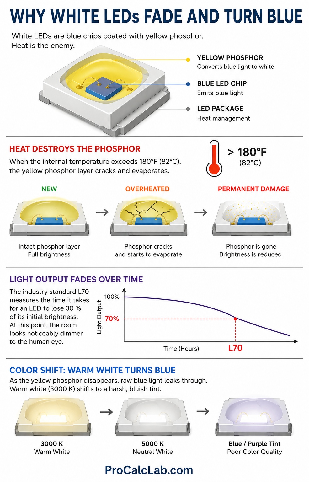
Following the brightness drop, a severe color shift occurs. Because the yellow filter is missing, the raw blue light from the underlying chip leaks through. A strip that started as a warm white 3000 K hue will slowly turn into a harsh, cold, purplish-blue tint.
| Core Junction Temperature | Expected Running Hours L70 | Visual Alterations |
|---|---|---|
| Below 130 F | Over 60000 | Absolute color stability |
| 135 F to 160 F | Around 40000 | Barely noticeable dimming |
| 165 F to 190 F | Less than 15000 | Noticeable shift to cold blue |
| Above 200 F | 1000 to 3000 | Complete phosphor destruction |
Density and Optical Blending
Creating a neon-like continuous line of light requires eliminating the zebra effect. This optical flaw occurs when individual bright spots reflect off glossy surfaces like granite countertops or tiled floors. The predictor analyzes the ratio between diode spacing and profile depth. A shallow channel measuring 0.2 inches deep requires a massive diode density of 120 per foot to blend the light seamlessly.
💡 Diffuser covers protect the circuitry from dust and help scatter the light. However, optical physics dictates that heavy diffusion blocks actual light. A dense milky cover provides perfect blending but traps up to 40 % of the lumens inside the channel. Installers must purchase stronger strips to compensate for this heavy absorption.
| Diffuser Style | Lumen Absorption Rate | Blending Performance |
|---|---|---|
| Heavy Opal Matte | 35 to 40 % | Erases all individual dots |
| Medium Frosted | 18 to 20 % | Softens light but structure remains |
| Microprism Texture | 10 to 12 % | Focuses beam with minimal loss |
| Clear Polycarbonate | 5 % | Maximum output with zero blending |
Impact of High Color Rendering
Modern architectural lighting demands strict color accuracy. A CRI 95 fixture makes red apples look vibrant and wood grain look rich. Achieving these high ratings requires applying a significantly thicker layer of phosphor over the bare chip. This thick chemical blanket severely restricts heat dissipation. A high CRI strip will naturally run hotter than a cheap CRI 80 alternative drawing the exact same wattage. Furthermore, the thicker coating physically blocks more light from escaping. System efficiency drops notably. Expect a 20 % penalty in total brightness when upgrading from CRI 80 to CRI 95.
Binning and MacAdam Ellipse Sorting
Semiconductor manufacturing is an imperfect process. Growing microscopic crystals yields chips with varying voltage requirements, brightness levels, and color tints. To manage this chaos, factories sort chips into specific performance bins. The highest quality metric for color consistency is the MacAdam Ellipse step.
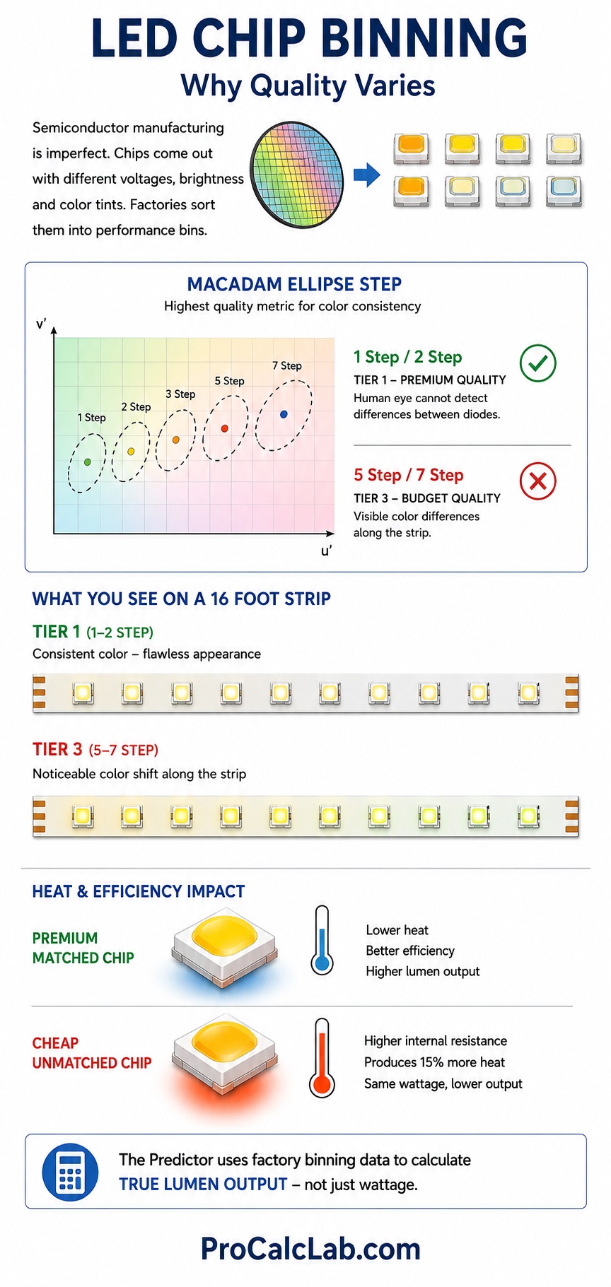
A 1 step or 2 step MacAdam sorting represents Tier 1 premium quality. The human eye cannot detect color variations between diodes on a Tier 1 strip. Cheap Tier 3 strips often use a 5 step or 7 step sorting process. On a 16 foot run, a Tier 3 product will show severe color shifting. Diode 1 might glow warm yellow, while diode 50 glows slightly green. The predictor utilizes this factory sorting parameter to calculate true lumen output. Cheap chips suffer from higher internal resistance, producing 15 % more heat than premium matched chips operating at the exact same wattage.
Voltage Drop and Wiring Resistance
Long runs of low voltage tape suffer from electrical resistance. The flexible copper base inside the strip carries the current. Budget products use incredibly thin copper layers weighing just 1 ounce per square foot. Pushing high current through thin copper generates parasitic heat. The copper trace itself becomes a heating element, baking the diodes from below.
Vdrop = I * R * L
Where V indicates lost voltage, I stands for electrical current, R is the resistance of the copper, and L is the length of the run. A 16 foot run of 12 Volt tape will lose significant voltage by the end. The diodes nearest to the power supply will receive a full 12 Volts, while the diodes at the far end might only receive 9 Volts. This results in uneven brightness and massive color deviation across the room. Professional installations utilize 24 Volt or 48 Volt systems with 3 ounce copper boards to completely eliminate this issue.
Pulse Width Modulation Dimming Stress
Dimming these systems requires specialized controllers. Traditional wall dimmers lower the voltage. LED controllers use a technique called Pulse Width Modulation. The controller rapidly cuts the power on and off 100 or more times per second. Human vision averages these rapid flashes and perceives a dimmer constant glow.
This rapid switching causes microscopic thermal shocks. During the 1 millisecond the power is on, the chip takes 100 % of the maximum rated current. Cheap controllers operate at a slow 300 Hertz frequency. This slow switching causes audible buzzing in power supplies and stresses the internal wire bonds of the diode. Commercial grade controllers operate at 2000 Hertz or higher. High frequency switching drastically reduces component fatigue and extends the overall life cycle.
COB versus CSP Technology
Traditional Surface Mounted Device chips place the semiconductor inside a square white plastic housing. This plastic acts as a thermal barrier. Chip on Board technology eliminates the plastic housing entirely. Up to 300 bare chips are soldered directly onto the flexible copper board. A solid line of yellow phosphor covers the entire array. COB strips feature densities of up to 200 chips per foot. They deliver perfectly flawless continuous light even in ultra thin 0.2 inch profiles.
📈 Chip Scale Package technology represents the absolute cutting edge. The semiconductor itself acts as the structural housing and electrical contact. Without delicate gold wire bonds or plastic casings, CSP strips survive extreme mechanical bending and thermal loads. They dissipate heat instantly into the aluminum backing. For projects demanding maximum longevity in harsh environments, CSP remains the ultimate choice.
Practical Calculation Example
Consider a kitchen under-cabinet lighting project. The goal is bright task illumination on the countertops. The chosen strip features SMD technology with 36 diodes per foot. Power consumption is 4.5 W/ft. Efficiency is rated at 120 Lm/W. The distance from the cabinet bottom to the counter is 1.5 feet. The installer plans to use a shallow aluminum track with a 0.5 inch depth and a standard frosted cover.
Entering these exact values into the tool provides immediate feedback. The uniformity status displays a warning. The 0.5 inch depth combined with 36 diodes per foot is insufficient to mix the beams. The counter will reflect individual dots. The frosted cover absorbs 18 % of the light. Despite the loss, the final illuminance on the work surface remains excellent for cooking tasks. The junction temperature stabilizes in the safe zone around 125 F. The estimated L70 lifespan exceeds 50000 hours. The color output will remain perfectly stable for 20 years.
If the installer decides to swap the strip for a high-power 8 W/ft version to get even more light, the calculator will immediately flag a thermal warning. Pushing 8 Watts through a tiny 0.5 inch profile overwhelms the aluminum mass. Junction temperature will exceed 170 F, reducing the lifespan down to 18000 hours and triggering early color shift.
Recommended Reading and Reference Literature
- Architectural Lighting Design by Gary Steffy.
- Solid State Lighting Reliability by W.D. van Driel.
- The LED Lighting Book by Fred Schubert.
- Thermal Management for LED Applications by Clemens Lasance.
- Light Right: A Practicing Engineer Manual by James Benya.
- Illumination Engineering: From Edison to the Laser by Joseph Murdoch.
- Optoelectronics and Photonics by S.O. Kasap.

David Parry — Senior Engineering Analyst
Specializing in electronics and physics-based simulations with 20+ years of engineering experience. David ensures the mathematical and physical accuracy of the tools at ProCalcLab.